


Rotary Ninja
-
Posts
1,310 -
Joined
-
Last visited
Content Type
Profiles
Forums
Downloads
Store
eMastercam Wiki
Blogs
Gallery
Events
Posts posted by Rotary Ninja
-
-
Added a few words for a.....
Welcome to the forum fiss!

Stop putting bad words in my mouth!

-
Wow. I see you have already been down this road. Interesting that they haven't fixed this. Of course I figured they would fix it by X2 so I never said anything. Then X3 came along and I thought they would fix it in X4. Etc. So here I am. There are worse things to complain about. But right now I can't think of any.
-
I haven't looked at the part since I don't have Mastercam 6 on my box yet... but have you used the Trim toolpath before? It sounds like you have one boundry you need to cut inside of, then another you want to stay away from?
Another way I avoid areas in Z axis is on the Rough Contour Parameters tab click the cut depths button. Set it to Absolute and right click in the Minimum Depth box and select "Z = Z Coordinate of a point". Pick the top of the surface where you want to start cutting then subtract your depth of cut. So if the top of my surface is -Z- 0.0000 and my cut depth is .100" this field will read -.1". Then do the same thing in the maximum depth, then if you need an overlap subtract that. So if the lowest area I want to cut is say -4.0000", and I want my tool to cut past this by .100" this field will read -4.1".
-
3. when you have xform translate 3d (or whatever) window open, just hit the green check without changing anything... i.e. from top to top... the selected entities will turn purple(unless you changed your default xform result color) then in the general selection bar, click "all" and in the window that pops up, click the xform result button at the top.
HTH!
And yeah, I saw this. I will try to start doing this. This is just a work-around though because it still requires another step. Because after clicking the wrong command you have to select ALL>>>Xform Result. Then Xform>>>Translate. If the entities just remained selected I could just go Xform>>>Translate. So yes, that works. But my solution is still faster.
-
So do you know how to use the tool I spoke of / just wondering.
Yeah, I have used it, but I haven't messed with it a lot.
You know, you can change your toolbars to be just the way you like them. I don't use it either so I removed it from my toolbar. My toolbars consist of only things that I use. I always change c-planes and rotate. For the five times a year that I have to do that, I can do it quicker than figure out the latest method AND remember to use it.
I have minimal toolbars on my screen as well. And each bar is customized. I don't use the Xform bar... I use the file menu for that one because I generally don't move things around too much after I get my setup figured out. Old dog, new tricks kinda thing ya know. I have been that way for years with Photoshop, Autocad, Dreamweaver, etc. And I rotate my parts the same as you.
RE: pre-selecting, then selecting the wrong icon and losing your selection on exit...I could be wrong here because I'm going from memory, but when you realize you've selected the wrong icon, try hitting Esc once to back you out of it and see if you still have your selection.
ESC clears your selection as well.
As far as selection goes, I rarely have a selection that I can't pick pretty darn quick with any combination of chain manager, quick mask, window (maybe even from the front view or whatever), all-menu, invert-selection, and Alt+E.
I am good with all the selection techniques. I love Mastercam's intersect, in+, out+ etc. I use the polygonal selection tool a lot as well. I learned years ago in Photoshop that being able to select things well is the key. So I have no trouble there. I use levels, groups, and all the other things to seperate my entities for faster re-selection. And the "Hide Entity" button is worn out on my toolbar
.gif)
But there are times when it still takes time to select entities in a model. And there are times when clicking each entity is the only way you are going to select them. Especially some of the models we get. I just think that until you perform the command on something it should remain selected. Nothing should ever de-select without me de-selecting it or doing something to it to make it a "Result".
I know if I pick my command first, then select my geometry I could solve this dilemma. But I never do it that way. The order I do things is the way you have to do them in other programs. You can't pick a command in Photoshop and have it ask you what to perform the command on. It just doesn't work that way. Photoshop won't even let you select most commands until you select something. A lot of other software is that way as well. So to learn to do it in reverse after 20+ years of using other types of software just isn't going to happen.
-
Yeah I figured that much out after I had already edited the 40 points. I then had to edit them again. Was just wondering if there is a setting to correct this?
-
I am looking into the Okuma VTM100 now. I'm wondering how they will compair in price. Also how does the service side of it compair? Has anyone had any experience with the Hyundai, Doosan or Okuma service end of it?
I have been machining for over 15 years now. I have ran over 30 types of machines from Cincinatti, Haas, Mori-Seiki, Okuma, Karaki, Mazak, Century Turn, and a lot more. To this day I still tell people Okuma is one of the best machines in the business. I never had one slow down on the heaviest of cuts. They are very solid machines. I used to run parts with .0002" tolerances and never worried leaving .002" for a gage cut. Amazing machines. But pricey. The Century Turn VTL's I ran had Fanuc controls and were very nice as well. I used to rough .450" per side at .030"/rev in 718 Inconel. And the machines did fine.
-
Well at least I learned something. =)
I suggest getting away from this old tool and go with Dynamic Xform faster easier to use.
Can anyone tell me why using translate 3D is any better then Dynamic Xform?
I don't use translate 3d. I always click it by mistake when trying to click xform>>>translate is what I was saying.
-
First of all, I suggest you start a forum for suggestions
Here are a few things I would like to see added/changed in future versions of Mastercam...
1. Ability to adjust the feedrate and RPM of the first pass through a pocket in the toolpath parameters. The first cut is always a slot, cutting the full width of the endmill.
2. Spring passes on a contour. Leading in and leading out takes up time if all you want to do is make another lap. It is a feature on a pocket. Why is it not on a contour?
3. When I spend 10 minutes selecting entities then click XFORM>>>TRANSLATE 3D and close the dialog because I meant to click XFORM>>>TRANSLATE all of those entities I had selected de-select. It really sucks that I have to re-select all those entities again. Keep the entities selected until you actually do something to them.
I know I have more to add to this but right now this is all I can think of.
-
I have a parallel pocket toolpath cutting 4 pockets. The first -X- move after helixing down into the pocket is basically a slot move cutting the full width of the endmill. I used the "Toolpath Editor" to edit the toolpath to slow the feed down on each of these pockets just for the first -X- move through the pocket since it is a rather aggresive feed and depth of cut. Since there are 5 depth cuts per pocket that was 20 points that I slowed the feedrate down, then 20 more that I sped it back up after this initial slot. After posting I found that the coolant was turned off at each of these edited points and never turned back on. Is there something I am doing wrong?
-
Greg I have asked a few times the same question it is funny some times the answer you get.
I have even asked how fast do you run a indacator in mill with answers like 100 rpm.. lol
It's only funny because, like me, you have unwound your spring a time or two
-
Here's what I think makes for a good machinist/programmer (being one myself)...
The absolute biggest credit to my skills has been the people I have worked with. I learned a lot from them. So ask about their machining background and maybe what they learned from who. Ask them to give examples. If they have the skills you are looking for and they say anything remotely close to "This one old guy showed me..." hire them. It means they LISTENED! These old guys and their skills are disappearing fast! Finding someone who can bring some of that experience into a shop is going to benefit your current and future employees.
I like the idea of giving them a print and asking how they would machine it. Have a couple examples. Have one print of a simple to machine part, and maybe one you have machined and had a little trouble with. See what kind of ideas they come up with when put on the spot. Keep in mind though, most fixture ideas don't come to mind right away. Someone who recognizes machining a part is going to be a pain may be a better choice than someone who is cocky and spits out an idea right away.
-
 1
1
-
-
Here is what I came up with...
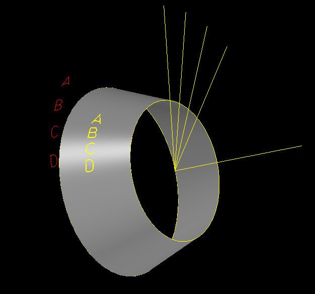
I have also attached the MCX file.
I am sure there are different ways to do this, but my solution was to create each letter at the same X/Y location. Switch to the left view and rotate each letter 12 degrees from the previous letter. I then created a view at each of these rotations and projected the letter onto the surface.
-
gcode solved this in the middle of my reply lol.
-
Well, I offset the contour -.010" and rechained it and got all G03's

I thought now I am onto something! This wouldn't work of course because your part ID would be .020" small. But this was just a test. I then went into the toolpath parameters and on the contour paramaters page I changed the stock to leave on walls to -.010" so the tool would cut to the proper dimensions. I then got the G01's again
 I even chainged the arc filter total tolerance to .0002" thinking maybe that would fix it, but it didn't.
So I went back to your original program and the only thing I did differently was I changed the stock to leave on walls to .0020". The area that it posted with the G01's became a lot smaller. So I tried .0025". The G01's went away. So you could offset your tool -.005" on diameter and get a good part essentially.
That still doesn't explain why this is happening though

-
This is really weird. I have recreated the file from scratch. Used tools from my own library. And I get the G01's still. I have a couple more things I am going to try.
-
I posted using a generic Haas post and our modified Haas post and I get G01's as well. I then used a generic Fanuc post and got no G01's just as gcode did. I have never seen this either. Will mess with it more in a bit and see if I can figure this out.
-
I think he is saying his arc moves are in small -x- and -y- increments instead of G02's and G03's. Would be my guess.
-
I see manuel beat me to it =)
-
If I can't get a tool path to do what I want I draw a custom tool path and project it onto the surface using a surface finish project tool path. Using this tool path you can get some pretty good results. I modified the previous MCX file for an example. This tool path would have no mis-match.
-
For chamfers I use the Spot Drill tool in Mcam, which defines the tool as having a sharp point. We use a 90 deg 5/16" mill drill for everything from spotting holes to chamfers and deburring. These have a small flat at the tip. I touch the tool off then raise the tool offset by .006". Then I program my chamfers exactly as stated on the blueprint and I usually end up with chamfers very close to what they should be. Works great.
-
Make sure you are not linearizing arcs.
If you don't get helix output, look into your control def >> arcs make sure helix support is ticked on
Just noticed this wasn't enabled in our definition. Will try this method as well. Thanks.
-
There is a check box on the lead in/lead out tab of the thread mill parameters.
If you are getting helix code your Haas may not be interpolating them good enough. In that case you may want to force linear output but make sure the toleance is small enough to give you acceptable results, I use .0001" in this case.
This worked. Thanks!
-
I am cutting a 2-7/8 - 12 OD thread on a Haas VF-2. The cutter is a single point style solid carbide cutter and has 6 teeth (like a key cutter). We use these with good results on most threads, but on the larger OD threads we get a lot of what looks like splines in the thread. There is no filter for thread milling. Is there any way to make the threads look smoother?
We are still using X5 but have X6 in the box ready to install.
Mastercam Feature Suggestions
in Industrial Forum
Posted
I Never knew that button was there. That will help. Thank you!
FWIW - I still wish the entities would remain selected after effing up =)