


balnh
-
Posts
114 -
Joined
-
Last visited
Content Type
Profiles
Forums
Downloads
Store
eMastercam Wiki
Blogs
Gallery
Events
Posts posted by balnh
-
-
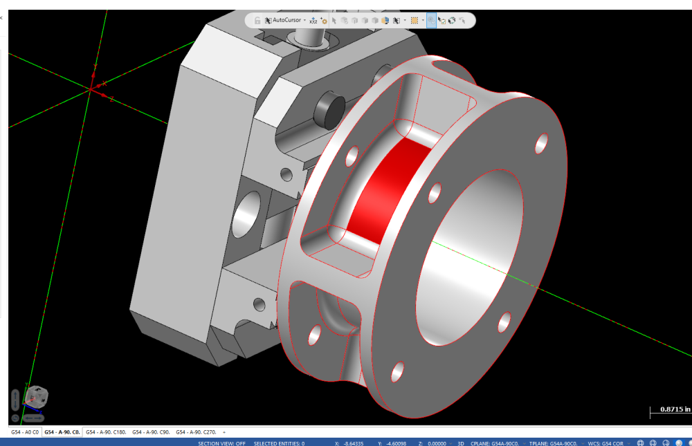
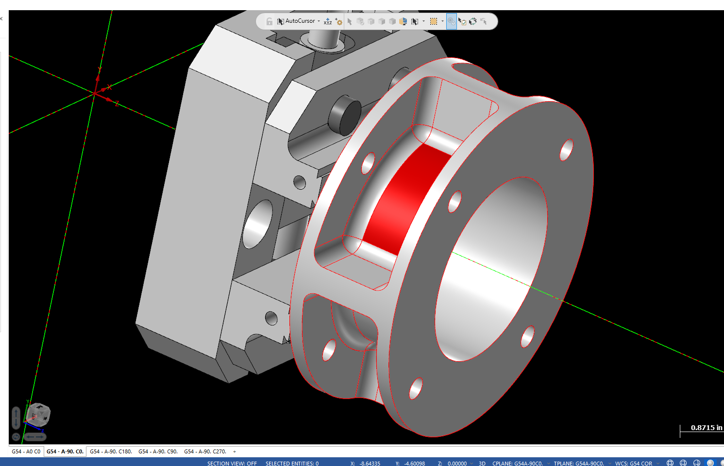
Here is a screen shot. The feature in question is the red face. The part sits on center on the COR. The undercut is concentric to the bore and outside. No angles on it just a cylinder.
-
 1
1
-
-
4 minutes ago, crazy^millman said:
Generic Post says it all to me. No File sorry not in the mood to play 100 guesses.
Fair enough, that’s what I figured with the generic post.
-
9 minutes ago, JParis said:
Without seeing the geometry it's impossible to say but I wonder if this is something rolled/unroiled geometry could help with...
I did unroll the geometry, created a flat surface from the wireframe. The code posted from the 4th axis haas post I have is short and sweet. That’s subbing the Y for A.
-
I have a simple toolpath that’s posting with many breaks in the C axis motion. I am using generic Fanuc 5 axis post. Subbing x axis for C on a table-table AC machine. I did a search and read about brk_mv_head and brk_max_ang. I set them to 1 and -40 respectively. Did not change output. I tried different combos and didn’t affect output at all. I downloaded the newest 5 axis post from the Mastercam website and got the exact same results. I posted with 4axis haas post and got perfect nc code. I have come across this in the past and I was only doing some deburring and didn’t think twice, this toolpath is a flow line so it’s taking about 30 c axis moves to move about 60 deg or arc. Just mildly annoying but the machine will run the program. Is this something in the post that can be fixed?
Thanks
-
15 hours ago, cncappsjames said:
MACRO Eng. Manual;
https://www.dropbox.com/s/hwyj586orrp5lhe/Macro_Eng Supplement.pdf?dl=0
Macroi Training Presentation;
https://www.dropbox.com/s/ntuzs1roz895fqd/MACRO_Training_Rev1.pdf?dl=0
DOC CD
https://www.dropbox.com/sh/wrp4bqrhuh71vky/AAAshjUbMCwKU7H1bfTW8rQka?dl=0
Advanced Programming Guide;
https://www.dropbox.com/s/c5dfnbku2kqmudg/Advanced Programming Guide - 6AB10.pdf?dl=0
Core Programming Manuai;
Awesome, I appreciate this. I have a lot of reading to do.
-
1
-
-
Thanks for the reply. I have a Sinunerik manual that I downloaded but the Yaskawa/Siemens manual that came with machine doesn’t have much information in it. I do have the Yaskawa/Siemens “Supplementary explanation for Macro Porgram”. Thanks for the help and nice in the right direction.
-
Shop I work in has a Matsuura With Siemens 840 control on it. Never had the need to run any macros on it but I plan to convert some Fanuc macros to run on his machine. It’s not running in Siemens Mode so it’s just running Fanuc/Yasnac g code. I started to convert the variables from From #100 to Y_[100] format. The arithmetic and Other functions seem self explanatory. My main question is What’s the format for an address like Z#100 or X#101? If anybody can point me on the right direction I appreciate it.
-
47 minutes ago, Werktuigbouwer said:
Try the following:
Look at the sextaux$ and sextsub$ line
pheader$
   result = setncstr(two, spathnc$ + snamenc$ + sextnc$)

psub_st_s$
      result = fclose(spathaux$ + snameaux$ + sextaux$)
      snameaux$ = drs_str(two, sub_prg_no$)
      sextaux$ = ".nc"
      result = setncstr(two, spathaux$ + snameaux$ + sextaux$)

psub_st_m$
      result = fclose(spathsub$ + snamesub$ + sextsub$)
      snamesub$ = drs_str(two, main_prg_no$)
      sextsub$ = ".nc"
      result = setncstr(two, spathsub$ + snamesub$ + sextsub$)
Thanks. That did it. I appreciate the help.
-
1
-
-
Lol I didn’t even think to look there, thanks Millman. ...But it’s set to .nc
The main programs post with a .nc but the subs post with a .sub extension.
-
Good morning, I messed around with a post to post subs as individual programs. I followed the instructions in this link:
https://forum.mastercam.com/Topic24759.aspx
Posting works as planned except it posts with a .sub file extension. What do I need to do to post out subs with a .nc file extension.
Thanks
-
I use 2 and 3 flutes for aluminum, I’m not familiar with c103 but it doesn’t sound like it’s any fun. Treat it like 316
-
I’m not familiar with that alloy. For pure niobium I would use carbide if I could, and ramping not plunging. I treat it like 316. Drilling with high speed drills just kind pushed the material and left a huge mushroom. Fortunately I only have to go -.125 deep so I circle milled the thru holes.
-
Here’s how to go all G154 from MPmasterif haas,
[
p_wcs = workofs$ - five #G154 P1 to P99
"G154", *p_wcs
#g_wcs = workofs$ + 104 #G110 to G129
#*g_wcs
]
You can download the post from this site
HTH
-
I’ve done a fair amount of small electronic packaging out of this stuff. For endmills I used 4fl Altin or Tialn coated. 150-200 SFM IIRC.
High copper content isn’t bad at all like 70/30 or 80/20 WCu. It’s a tad abrasive. 90/10 is very abrasive. The higher copper alloys I’ve drilled with regular Hss no problem but the 90/10 wore out the corners pretty badly.-
1
-
-
31 minutes ago, htm01 said:
i get that all the time from one operator,
"something's wrong with your program"
ooook , let's check your tool offsets, your fixture offsets, are you running the correct program, did you even read your set up sheet ?
My favorite is when someone blames the machine for acting up.
“ I added -.020 to the wear comp and it’s not opening up.”
Then I take a stroll over to the machine and see that he’s been putting the value in Length wear. This has happened twice.-
1
-
-
2 hours ago, OVodov said:
Many years ago we used macro for that.
So coordinates of center of rotation was kept in G58.
The macro took coordinates of part G54 or G55 calculates according to G58 and rewrite new coordinates for each position to G59.
We used it in another software but when i asked In House Solution they made similar postpsossesor for 4 axis.
On 2/20/2020 at 3:49 AM, Günther Massimo - GMCCS said:usually this is an option and musst be activated in your controll. However, if you don't have this option at all, you can achive a dynamic workoffset with a macro.
I don’t want to hijack this thread but I’ve been thinking about doing this for our trunnion. Is it as straight forward as solving for new point and overwriting offset or using G52 and shifting current Workoffset? Which order of solving if rotations don’t intersect?
My A Axis Z is -.0045 below C axis and Y-.0008. I thought about the math to figure points but my mind just stops at a certain point when I think about this shift. Right the now programming with COR the post handles this shift and everything is sub .001.
-
2 hours ago, 5th Axis CGI said:
Don't you love how he comes back and answers you? Then it will be a few weeks before the next panic attack and then he will be back with more things off on different tangents.
Lol no skin off my back.
-
You might not have the macro option on the machine if it’s giving bad code alarm. You do have inspection plus in the machine correct?
-
Never mind just found it. Navigating without the touchscreen is a pain in the xxxx though. Thanks
-
2
-
-
Has IHMi interface but not touchscreen.
-
6 hours ago, cncappsjames said:
Ok @Leon82,
- Press the button that has 9 filled boxes (looks like a negative of Tic-Tac-Toe)
- Press File Manager on the touchscreen. This brings up Windows Explorer
- On the left pane of explorer scroll down to the D:\ drive and double tap on it
- Navigate to D:\FANUC\iHMI\MTB\CNCOpera\Setting
- Double tap on Setting_Data.txt open with Word Pad (or notepad if you prefer)
- Scroll down to the following;
[Actual_Feedrate]
Max_Scale-Markings_Val=40000
Change 40000 to 1575
Tap File, Save, and save the file.
Close out of Word Pad (or Notepad). Close out of Explorer. Navigate back to your CNC screen. You may need to go to another screen to get the display to refresh. Hope that helps.
As to the keyboard not keeping up... I guess I type slower. LOL I did notice the computer doesn't seem to be quite as responsive as a dedicated PC or dedicated CNC. I'm going to do a little more testing between Christmas and New Years and see what I can figure out.
Will this work on a robodrill with 31i B5?
-
Try parameter 6001.6 set to 1 to retain variables.
-
Yes I Regenerated,
I set MR6 to 10. And MI8 to 3. Use_stk_typ set to 2 with 0’s in the Limits And it did not post the the safe retract at all.
I got good results with MI7=1, MI8=3 and set set use_stk_typ to 2. I set the upper limit to 10. And it did post Z10. at every Rotation Which is good.
-
Colin I did some testing and got the MR1 to work by changing the lim trip variables to 45. It works great on jobs I am currently running. During testing I tried MR6=10. with MI8=3 Got no additional safe level z retracts. The upper and lower z limit variables are set to 0.0 and use_stk_typ is set to 2.
I tried MI7=1., MI=8., and MR=10. and it did post with the MR6 retract Z10. but also add an additional Z0. Approach. Any thoughts?
Thanks for your time man I appreciate it
Axis Substitution posting in 1.16 degree increments
in Industrial Forum
Posted
I don’t have a multi-axis liscense. I ran the parts no problem, roughed with optirough with axis sub. My question was why does the generic 5 axis post break up the c axis motion so much with Axis sub toolpaths. My generic Haas 4 axis post posts nice short Nc code. I figured it was generic 5 axis post limitation.