


NOTW Programmer
-
Posts
469 -
Joined
-
Last visited
Content Type
Profiles
Forums
Downloads
Store
eMastercam Wiki
Blogs
Gallery
Events
Posts posted by NOTW Programmer
-
-
When you do that though sometimes you have to reclick on the tool in the toolpath properties or it wont update the H and D.
-
I have a pocket and somehow it misses one of the side walls, im using this routine to finish a floor. When I choose to enable the finish passes and use the finish outside boundary it enter the stocks on the corners 4 times.
-
It was in fact stripped out in X3, I wonder if it can be brought back somehow. Here is a picture of what we mean.
-
Hello Guys
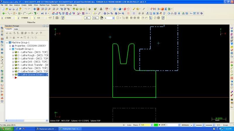
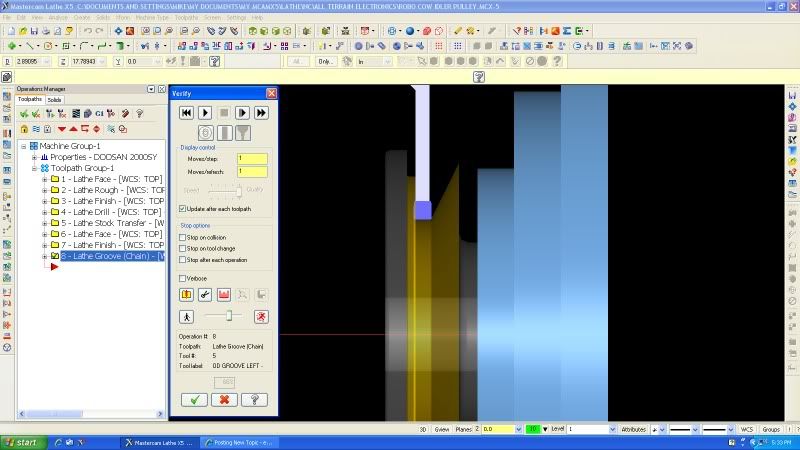
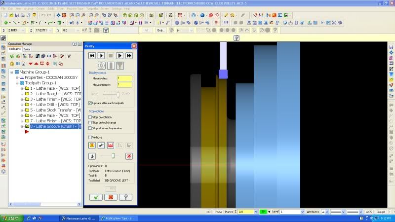
Im using X5 and all my rad's that need to be machined in the Sub Spindle seem to be reversed in the verify, and in backplot simulation all looks to be ok. It more less looks to be changing the rads into large chamfers.The contour has not changed at all just the tool path is out of wack, Has anyone seen this problem before??
Upload the MCX or give us the sizes so we can create a replica of the part and reprogram it.
-
Try using the standar pocket routine, it has an option on the tree for finishing and you can override the feeds and speeds for your Finish. You might have to use two chains ir order for the toolpath to only cut the wall you need.
-
Could breaking the arcs get you an extra line where the G40 does work, can you set the control to allow Comp to be turned off on arc ? I also use it daily without any problems, both perpendicular and at 90deg. Could be a bug in your post also.
-
Here's my X5 output.
%
O0000(T)
(DATE=DD-MM-YY - 15-10-11 TIME=HH:MM - 11:17)
(MCX FILE - T)
(NC FILE - C:\USERS\WILLIAMJ\DOCUMENTS\MY MCAMX5\MILL\NC\T.NC)
(MATERIAL - ALUMINUM INCH - 2024)
( T239 |  1/2 FLAT ENDMILL | H239 | D239 | WEAR COMP | TOOL DIA. - .5 )
G20
G0 G17 G40 G49 G80 G90
T239 M6
G0 G90 G54 X0. Y0. A0. S1069 M3
G43 H239 Z.25
Z.1
G1 Z0. F6.42
G3 X-.0625 Y-.0625 I0. J-.0625 F60.
X0. Y-.125 I.0625 J0.
X.1875 Y.0625 I0. J.1875
X0. Y.25 I-.1875 J0.
X-.3125 Y-.0625 I0. J-.3125
X0. Y-.375 I.3125 J0.
X.4375 Y.0625 I0. J.4375
X0. Y.5 I-.4375 J0.
X-.5 Y0. I0. J-.5
X0. Y-.5 I.5 J0.
X.5 Y0. I0. J.5
X0. Y.5 I-.5 J0.
G1 Y0. F30.
G41 D239 Y.5
G3 X-.5 Y0. I0. J-.5
X0. Y-.5 I.5 J0.
X.5 Y0. I0. J.5
X0. Y.5 I-.5 J0.
G1 G40 Y0.
G0 Z.25
M5
G91 G28 Z0.
G28 X0. Y0. A0.
M30
%
-
Search for scoolant on the psof$ and ptlchg$ blocks and change it as follows.
pbld, n$, "G43", pfzout, *tlngno$, tloffno$, scoolant, pstagetool, e$ -unmodified

pbld, n$, "G43", pfzout, *tlngno$, tloffno$, pstagetool, e$ - modified
n$, pfbld, scoolant, e$ - where pfbld is "/" and coolant is output on a separate line
Remember this has to be done on both the psof$ ans the ptlchg$ postblocks. This also depends on how you post is configured, this is off a Fadal post so Fanuc might differ. If so le me know and I can take a look at it.
-
Can you upload an image to get a better idea of what we are dealing with here.
-
Nope, as far as MCAM goes its a simple part transfer, the post has to be configured properly in order for your machine to do this correctly.
-
That usually happens when the entities are not at the same Z plane. Mastercam finds no intersecting entity so the only logical result is to wipe the entire entity.
-
Im running Windows 7 without any of these problems or the need to change any settings that make my screen look like the old Windows 2000. Why are some people having to change these settings, I have an Nvidia Quadro FX 580 and X5 MU1.
-
This is what my Fanuc Post Outputs.
T11M6
G0G90G54X5.5Y-1.0625S360M3
G43H11Z2.
G98G84Z-.5R.1F20.
X7.5
X12.25
X14.25
X17.0437Y-1.4783
X19.Y-1.0625
X21.
G80
M5
G91G28Z0.
G28X0.Y0.
M30
The only difference is the Z-axis Zero Return. Mine doesn't output G200, thats weird...humm !
-
Fire up the POST debugger and track the postblock that is outputting that line of code, you can then format the instruction to be outputted just like the second line Q value; not sure if changing the quantity of characters to 16 will fix the issue.
-
When I edited the POST for our Fadal it had spaces everywhere I had to modify the "sopen_prn" which had a space in the string itself "( " this was causing a boatload of spaces. You can either search your post for this and remove the space after the parenthesis “(“ or do as Guest_Jim Evans_* said and add the no_spc$ but you would have to add this in every line you want to remove the spaces from.
-
I actually did create a post to take advantage of this M97 feature for Haas almost ten years ago. I can't remember if it was Version 7, Version 8 or Version 9. It worked like a champ! It even used Haas extended work offsets G110 thru G129 (this was before Haas started using G154 P1-P99)
I also customized the drilling cycles to take advantage of Haas' various different peck drilling cycles such as G73-IJK, G73-KQ and G83-IJK.
I'm using X5 MU1 now and never did update it yet because I haven't needed it.
Are You Willing To Share, This Seems Like A Nice Post To Have. Ill Update It For Our Haas Since We Now Have X5 MU1 As Well But The Post We Have Is Not All There Yet. Ill Pit It Up On The FTP Once I Update It For You To Download, Thx!
-
 1
1
-
-
Just experienced this yesterday while editing the drive surface on a coupling. When trying to change it after clicking the white arrow the whole model showed up yellow instead of the rib I had originally selected. Wierd !
-
Do You mean live tooling or a Subspindle? If you open the .pst file at the very top all the capabilities are listed. It is an MPMaster so all options probably are on, however modifications to fit your specific machine will be needed; unless you like to edit code every time you post out a program.
-
I’m sure there is, it is a variable inside mastercam so I’m sure a comment output of it can be added. I will look into this a bit later and get back to you. Do you have any experience editing posts; there might be some slight modifications you have to make.
-
As you dimension you can type T and the dimension settings come up, on the left you can click on the dimension settings and adjust the resolution of your measurement to 2 places instead of 1 that you probably have right now.
-
You might have not chosen the correct driving geometry. A file or a Picture will aid us into better helping you.
-
You could also click on the line width setting in the print parameters page, then you get what you want without having to see big thick lines on your part.
-
We just got X5 and Im trying to set up our active reports. Everything has gone good but now Im on Lesson 3 (reports and subreport) and Ive hit a stopping point. It says to open ActiveReports_Designer.exe and that I did. But then it says to go to File, Open, and open TUTORIAL Setup Sheet (MILL-OPERATION_L3.rpx. I can't find this anywhere. Can somemone point me in the right direction? I really don't want to call my sales rep. He's sooooo dry to talk to. I fall asleep every time I have a question and he's not the best at explaining things.
Have you downloaded the active reports turorial from the FTP, if not here is the link ftp://mastercam-cadcam.com/Mastercam_forum/Setup_Sheets/. All the files needed should be there. The file is called CreatingSetupSheetswithActiveReports.zip, have fun !
-
Hello all. I'm trying to do a Solid Layout Drawing and have it drawn at a custom wcs. It keeps wanting to make the drawing on the Top wcs. I tried using the Change View section on the Solid Drawing Layout page but can't get it to work. Thanks in advance.
X5 MU1
Have you tried the remove view, select the view you want to remove; then click on add view and select your custom wcs. Should work no prob, let me if it doesnt; im on my way out but will verify it tomorrow.
Regards,
GM
MPSUBREP
in Post Processor Development Forum
Posted
I believe the zfeed or sfeed might be forced out by using the * before it, Im not near my Mastercam PC so when I am ill post again and give you the correct variable. All you might have to do is remove the * from it.