


K2csq7
-
Posts
2,511 -
Joined
-
Last visited
Content Type
Profiles
Forums
Downloads
Store
eMastercam Wiki
Blogs
Gallery
Events
Posts posted by K2csq7
-
-
2 hours ago, Greg_J said:
Too bad you can't save stock as a solid and save it to a level then rotate the stock on that level or something like that.
It will not help with the milling, but right click in the ops manager - Turning stock preview - hit the little arrows in the upper left to expand the window - select save geo - solids - choose the boundaries you want to get solids from and green check. Now you have a solid of the lathe stock....
The stock flip of a stock model being mirrored is a known issue.
You can get around this by using 2 stock models - 1 to get the stock to the point just before flipping the stock, and the 2nd to flip the stock. Do not include the stock flip op in the 2nd stock model, just use a custom plane to control the flip.
-
 2
2
-
-
-
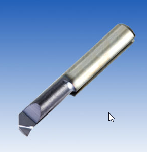
Use a Picco bar as a fly cutter?
-
1
-
-
Quote
im cutting it now by spiraling down about .01 per pass and its working but tapering about .01.
ive made the corners about 135 in mc so it can contour even though its very little.
Are you adjusting the feedrate for the tight arc motion? When swinging a tight arc, the OD of the tool is feeding around the arc at a much higher speed than the center of the tool. You may have programmed .0008" FPT, but swinging a really small arc will cause the OD of the tool to experience a much higher FPT (maybe up to .002"!!!)
-
1
-
-
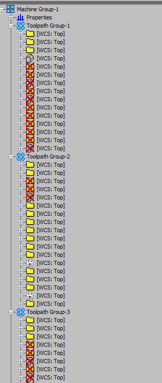
If all your ops are set to TOP wcs, right click in the ops manager, display options, shut everything off except the WCS;
Anything other than TOP will jump out at you.
-
 1
1
-
2
-
-
1 hour ago, Old_Bear said:
Done once and it's in there....that's something that is "supposed" to be opened up eventually and in truth, it needs to be, as does the ability to switch from a chuck to a spindle nose
That flexibility at the user level is highly desirable
You wont have to wait long!
-
1
-
-
6 minutes ago, #Rekd™ said:
While skiing??? :)~~~~
If we ever get some dang snow!!!
I was on the beach for new years eve, in maine... it had to be at least 285° Kelvin!
-
 1
1
-
-
My kids tell me the voice on this one is better;
https://www.youtube.com/watch?v=RXz6lOXkUTk
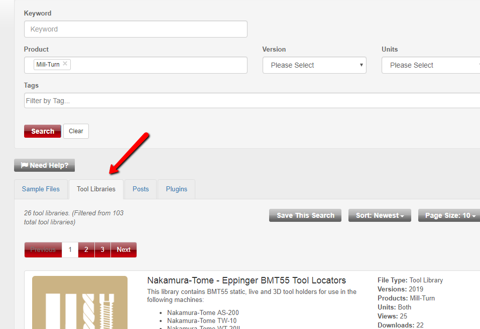
Also wanted to add we have a bunch of tool locator libraries on the Tech Exchange;
https://community.mastercam.com/techexchange#files
Happy New Year!
-
1 hour ago, Old_Bear said:
Home Tab
under Check Solid >> Curvature
^^^^ This.
If you don't have a solid, just wireframe like the picture above... Extrude it and use Curvature.
-
If you can't get it quick with parametric. Go with custom.
If you have 2019, make it 3d!
-
G68.3 is plane rotation using the current tool axis. (on an i-series)
-
Considering how often you backplot right after altering an op, we've got this available when you click backplot or post.
-
I ski in New England.
-
The SWF file should play in internet explorer, you may have to click "allow blocked content".
-
Not automatic by any means;
Use break at intersection from the trim/break menu, window select everything.
Then window select all the intersecting areas and hit delete.
-
Here's something to get you going. Your plunge and cut directions were set to opposite, tool clearance needed some rejigging, TNR on the model is zero so I set that accordingly, and I set your comp to "edge".
-
1
-
-
Also on the Mastercam website, in the Tech Exchange there are full libraries of the PrimeTurning tools in 3d.
Under support you'll find the Tech Exchange.
-
11 hours ago, motor-vater said:
First 2 parts came out with in the .001 tolerance,
Friggin kids these days with their fancy new computer machines.
When I was a kid, I had to move each axis in one direction..... uphill, both ways, in a heat wave blizzard.

-
1
-
-
Oh, and when you're picking up the datum the true position is called from, ensure you move each axis from home in only 1 direction......
What I used to do is pickup the center hole, set my work offset, send the machine home, then MDI G0 G90 G54 X0. Y0. and check the location, make G54 adjustments and repeat the process until that MDI command puts the machine dead nuts on the hole.
Also, keep the rapid override the same during the MDI command as you will have it when running the program......
(I drove a lot of loose machines) :rollseyes:
-
1
-
-
With the .001" positioning call, and the tight tolerance on the diameter (no max material allowance) unless your machine is dead nuts... hitting the diameters is the least of your worries.
Go home in XY, spot 1 hole, go home in XY, spot hole #2, go home in XY, spot hole #3...... also go home before drilling each hole. Machines are much more accurate with repeatability than they are with random positioning.
-
1 minute ago, AWL304 said:
is this what you are talking about (compensation)??
cant seem to be able to change option in lower left in compensation?
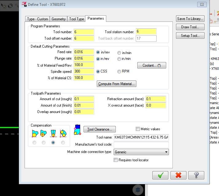
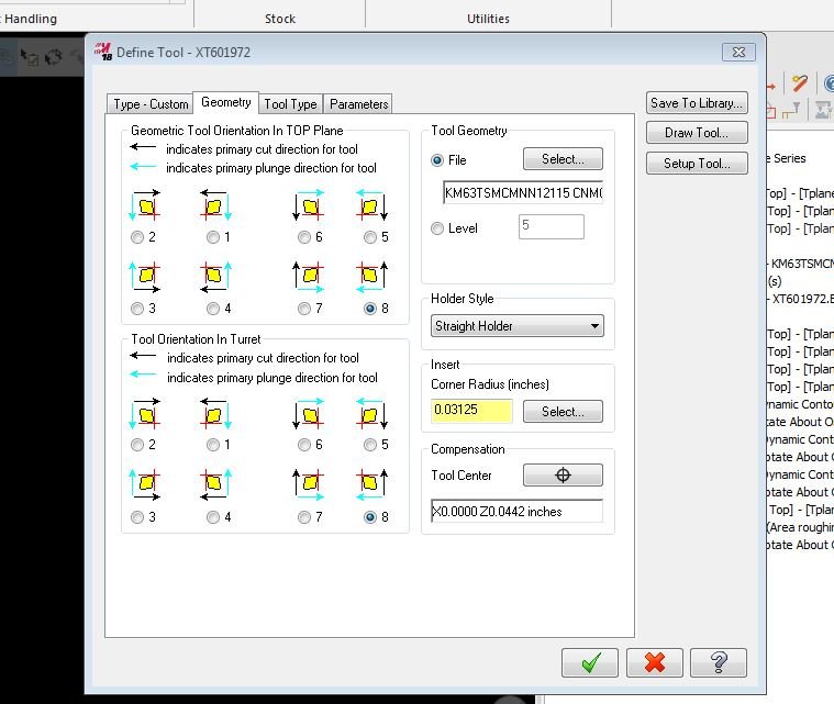
That's because it sees your "Tool Center" is on X0. Draw the tool with the entire TNR in 1 quadrant..... Think of the axis lines on the screen as the tool touch off points.
-
1
-
-
Op 1 uses tip comp, tool geo on level 2.
Op 2 uses corner comp, tool geo on level 3.
If you'd like to share your file, I will take a shot at what's going on.
-
On 8/31/2018 at 11:29 PM, jlw™ said:
Side note, score it all the way around and put upside down in a collet so that it breaks clean across.
I have done this successfully over a dozen times.
-
1
-
-
Drill a hole at the bottom of the groove, drop a Bull EM in there and hold on for dear life?
-
1
-
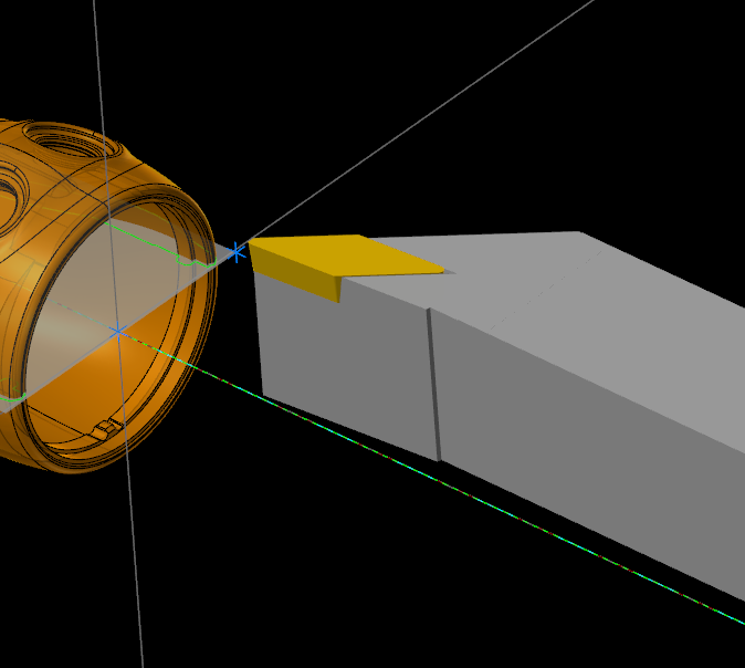
Mill-Turn tool locators for milling tools
in Industrial Forum
Posted
Hi Eric,
Milling holders are added within the ops, on the holder branch.