


ERIC14779
-
Posts
548 -
Joined
-
Last visited
Content Type
Profiles
Forums
Downloads
Store
eMastercam Wiki
Blogs
Gallery
Events
Posts posted by ERIC14779
-
-
YES... But I think that the Position feed back goes to the 3rd party Motion Control board.
how can I narrow down where the problem is when the machine is moved with 2 separate vendors equipment, embedded together ???
This issue is very low priority right now but when the next large part job comes in it will get important in a hurry !!
-
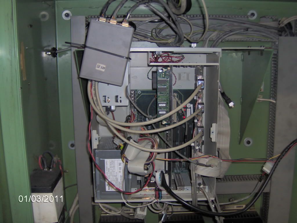
Well I do not think this Sharnoa Mill has a Fanuc Control I think it is all Sharnoa.
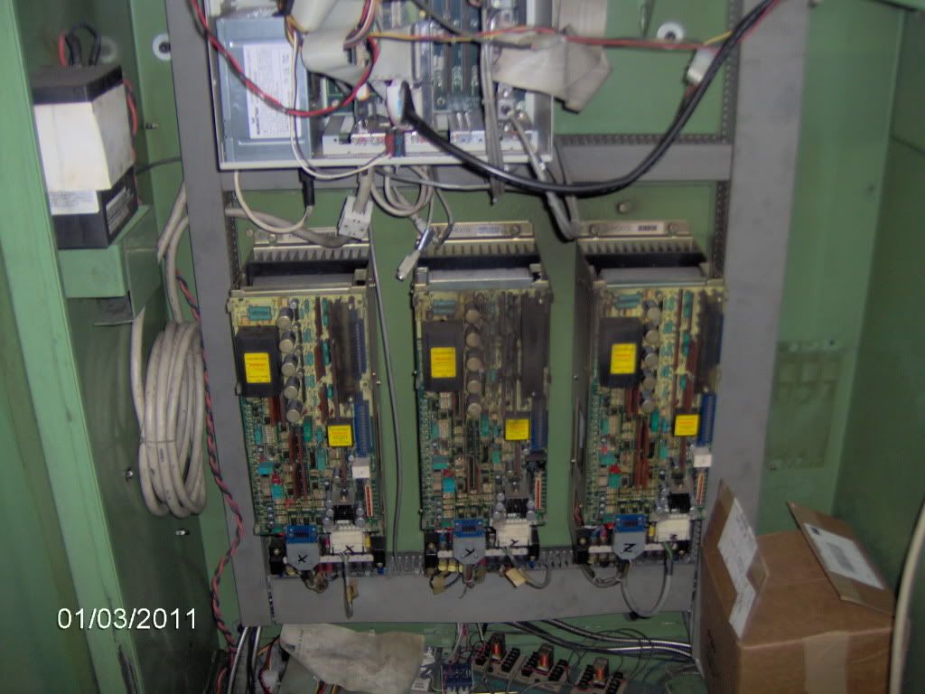
Only the Motors/drives are Fanuc, including the Spindle..
See the pics.
-
I am continuing my research.....
Again there is an additional resolver mounted above the Z axis ballscrew, I believe that it is coupled to it (the ballscrew).
and the cable from this device is connected to what I believe is a Resolver to Encoder converter then to the PC motion Card.
It looks like the resolver may have slip rings, and if bad, would this allow for progressive position deviation. and I would not get any error because the system is not set up to detect this deviation ??
UPDATE 0919 EST:
additional feedback is NOT a Resolver.
figured out that the "box" before the PC motion card is to supply the attached ENCODERS with 5 VDC from the PC power supply as there is a connector from the computer power supply plugged into it as well.
So it looks like there are encoders on X,Y,& Z connected to the PC Motion Card and then some connections to the Fanuc servo drives... But why then does Z drift farther and farther out of position ??? :-(
-
CNC Apps Guy 1,
be sure to read all my posts this morning....
To be clear,
this is a 1987 machine
the motor P/N is A06B-0652-B005 motor MFG date 9/86
I believe that the only Fanuc components are the drives --> X,Y,Z,spindle P/N A20B-xxxx-xxxx
and it has a PC based control (running Win98) Industrial PC w/Motion card and a Resolver to encoder converter ?? before the signals from the resolvers plug into the motion card.
I think that the tach and/or resolvers in the motors only go back to the Motor drives. and the PC motion Card instructs the drives to move axis...
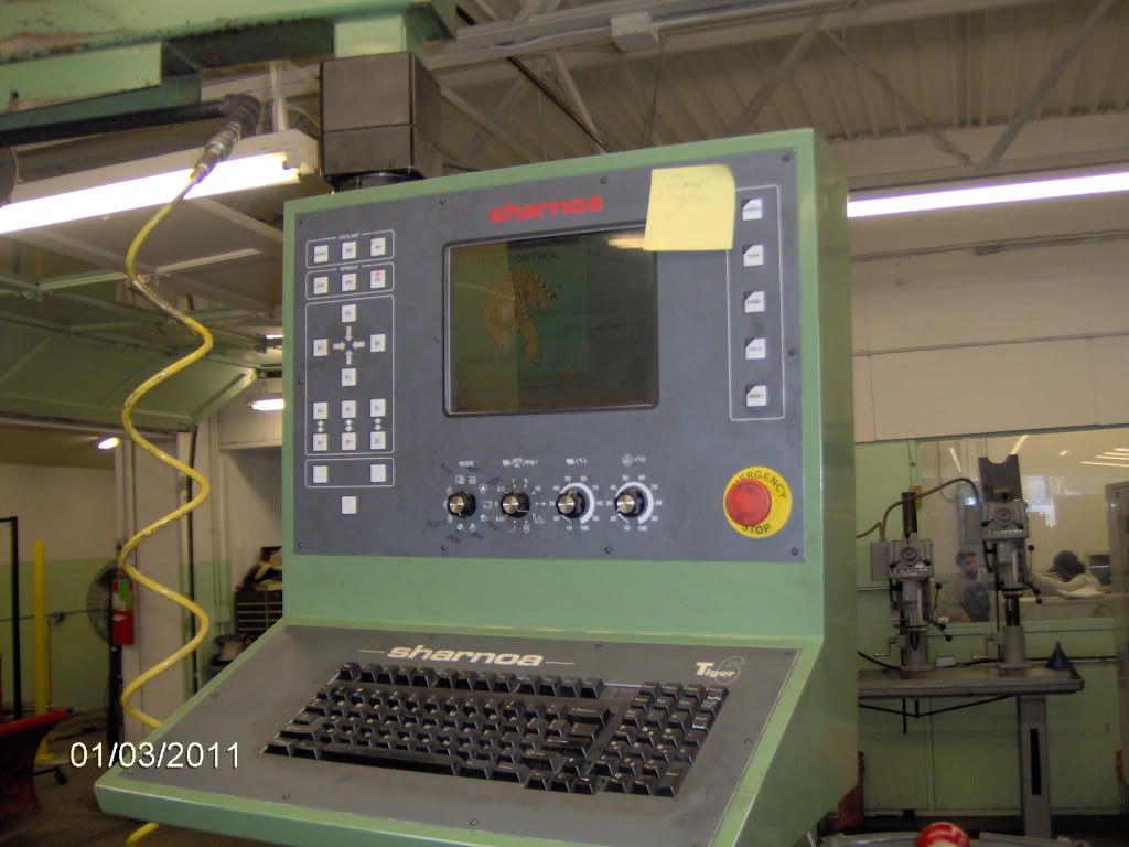
So I am not getting any Fanuc error codes on the control (Sharnoa Tiger 6)
A repair place I found on the internet indicated that the -B005 denotes a Tach.... ?? IDK..
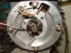
also I found a picture that said it was showing a tach on an old Gettys Fanuc DC servo motor, and what I saw on mine looked the same. See attached pic.
I am checking the motor brushes this AM.
UPDATE 0822 EST:
Z axis Servo motor brushes look good... still have about 3/8" of spring compression on all 4
Now what about the tach ??? how do I know if they are worn out ??
-
CNC Apps Guy
Are you talking about the motor or Tach brushes ??
-
Have an old 1987 machine with Fanuc A06B DC Servo system on it. the motors have Tachs as far as I can determine.
the motor P/N is A06B-0652-B005 the velocity Control is P/N A06B-6047-H003
I am trying to identify how this system works so I can troubleshoot.
On the motor under the yellow end cap is what I think is the Tachometer, looks like a motor armature with (from memory) 6 little tiny brushes around the commutator, then there is a aluminum plate, and the rest of the motor...
the endmost cable connector is attached to the Tach and the other has many large pins and at least 4 smaller pins (again from memory)
the "velocity Control" in the electrical cabinet has the incoming power, output power to motor and 2 connectors a blue one with many wires and a white one with 5 or 6 wires.
I have been trying to find diagrams and/or manuals on this Fanuc system to no avail...
the CNC control does not report any errors.... (Sharnoa Tiger 6)
any help to resolve this is appreciated.
-
UPDATE....
Got a email back from a Sharnoa service tech... he agrees that the machine is loosing encoder counts somewhere... (Yea no kidding)
now I have to find where.... anybody have experience tracking down this type of problem... I know to check wiring, connectors etc. is there a place that is more prone to a problem than any other on this machine ???
-
The Boelube type mister is the hot setup for cutting aluminum with high spindle speeds... sprays a fine mist of Boelube type lube at the point of cut... used it for 9 years it is AWESOME !!!
For routers you use light fast cuts you will have to experiment to see what your machine can handle. But I usually never exceeded 15,000 RPM usually around 12 worked for my machine... again you will have to play around and see what sounds/looks good with yours.
-
We have an old 1987 Sharnoa SDC-80D with a Tiger 6 control in our shop. We are using it daily again for a project. (It sits sometimes for months) and the operator states that the spindle seems to slowly NOT come all the way up to toolchange position ( a little lower and lower over time). And he has to re-home to get it back. and it does it again over time. He says he has to re reference the machine 2 to 3 times in 10 hrs. of running.
I have no experience with these Tiger controls and Sharnoa Servo systems, Can anybody point me in the right direction, and what to check ??
-
should I run max rpm (24,000).375" end mill, .375" depth of cut, 20 ipm, .05" stepover, use some of the Boelube paste, and watch it real close???
You call that light !!!! for a Thermwood I would try 3/8" ALUMINUM Cutting Carbide EM , 12000-15000 RPM 0.025" to maybe 0.050" DOC and maybe you can go 30 to 50 IMP
I had a Quintax Medium duty 5 X 10 X 48" Z machine and I could cut aluminum all day at twice this speed... but the Thermwood is half (at best) the machine the Quintax is....
Start ridiculously slow and light and work up.... Play with some scrap Aluminum.... and have some extra End Mills !!!
-
Boelube or similar makes a WORLD of difference to keep aluminum from welding on your cutting tools !!!!
Like CNC Apps Guy said the thermwood can only handle light cuts !!!! at best...
-
ref my post in the machining section
I have a 1987 Sharnoa SDC 80 50 taper machine....
yesterday I replaced the tool clamp cylinder(s) seals and reassembled with 0.050" clearance from the cylinder nose bolt to the tip of the drawbar...
today the spindle was making noise and the clamp limit was not making contact upon tool clamping. took the cylinder down and investigated it travels fully... measured the clearance and there is about 1/8" interference !!!!
Does anybody have a drawing of the spindle assembly that I can see if there is adjustment on the spindle "pack" as well as the cylinder.. there is a threaded bar coming up out of the drawbar I want to be sure that I can adjust this for clearance...
thanks.
-
The thread milling seems to me to be the best as well... backlash in any RAH will wipe out the threads... I think...
I will try to sway the Operator to give up on a Threading cycle and go with milling the threads in..
any suggestions for a thread mill vendor for 6-32??
I do not know what the material is yet.. I do not think it is anything exotic..
-
The operator was thinking he may be able to write a canned cycle or macro that would do XZ or YZ tapping.. I have zero experience with any of the Sharnoa controls (again this one is a Tiger 6)
is this an option ??? (writing a canned cycle)
-
-
-
Robk,
Yes I cringe at the thought as well but I am exploring....
What if I used a old school "floating" tap holder....
-
Anybody have any idea if this machine is capable of doing XZ and/or YZ plane tapping cycles ?? I have to tap a lot of 6-32 holes and I am planing to use a right angle head. The parts have to orientated so that I have to tap in the XZ or YZ plane...
Is this possible with out a lot of headaches ???
-
Thanks....
I looked on their site they do not stock 13 degree cutters... 12 then 15....
any other suggested vendors ???
-
Looking for a 13 Degree included angle 0.093" Tip Endmill 1 5/8" LOC minimum
HHS or Carbide 3 flute prefered... are there any non custom sources ??
Thanks
-
Check into Quintax
made in USA in Ohio....
-
Phil,
I have used one for about 1 year what are you scanning ??
I also have/use the RapidWorks software..
-
OK any smaller that can do this ???

Mid 80's Cinci Rotary Surface Grinder Mag problem
in Machining, Tools, Cutting & Probing
Posted
Hi all,
We have a mid 80's Cinci Millicron Rotary Surface Grinder that the Neutrofier II mag control seems to be acting up.
the Control Station Mod # is 17RC3E
when the chuck is operated at between 20 to 30% power it buzzes, on random occasions.
I have to look into this and we do not have any data on the Electromatic Neutrofier system.
anybody have any ideas as to how I should proceed to troubleshoot this ??
thanks in advance.