


Bret Vanderhyden
-
Posts
21 -
Joined
-
Last visited
Content Type
Profiles
Forums
Downloads
Store
eMastercam Wiki
Blogs
Gallery
Events
Posts posted by Bret Vanderhyden
-
-
Beautiful artwork, Bret!
This looks like a perfect application for Mastercam Art. You probably want to talk to your reseller about a demo on it.
The quick version is that you create an art "object" (basically a mesh in the background) that you can manipulate using repeating patterns, importing gradient graphics (white is tallest, black is lowest), etc. to get the size/shape/height you want. Then you can export that to a mesh or Mastercam surfaces.
Here's an example of something I created in a few seconds. I'll send you a PM about how to get the file, even a small one like this is ~15mb, so too big to attach here.
Start with a area you'd like to fill in (a simple rectangle in my case), and an area you'd like to fill in (the squiggly area in the middle):
Then go in and create a pattern (either use a predefined or go with custom). If you go with custom, choose your base image:
Finally adjust any settings you'd like to fill in the pattern until you're happy, then right click on the art "object" and choose to Export to > Mastercam Surfaces:
Now you can use an ol' toolpath to cut it, I used surface high speed raster here with a basic ball mill just for example:
Hi Aaron- thanks for the info on Mastercam art -- I'll definitely look into it.
-
oh you don't have the CAD of the finish model with that wave pattern. All of my ideas are driven to the Drive faces or surfaces so without having an accurate model that makes more sense to me now why you are taking this approach. That's impressive work man for not getting accurate CAD models, I would probably still model the part and use a 3d path than try to manipulate a manually drawn path but it looks like you have your strategy figured pretty good. Other than the toolpath editor idea, another thought would be to just use your custom geometry that you have drawn, but instead of doing it all with 1 toolpath break it up into multiple toolpaths and as long as you don't draw your links Mastercam should use a retract back to your toolpaths clearance plane. So my idea would be just don't use your links that you have drawn but instead use multiple toolpath and that should link the paths with a rapid move. good luck
Thanks Josh - Multiple toolpaths with rapid retracts is typically what I do. Window select works best for multiple entities.
-
I'd be willing to help. You asked, I offered. I've done quite a bit of stuff like this and am not interested in playing with it. If you have something specific post it, if not I can't help.
Thanks for your willingness to help. It'd be great if you had any insight on my initial question. Do you have any pics of stuff you've done?
-
I'd wear that shït out. Post some solids.
these are customers solids, I'm not going to post them. You can make your own revolved bottle shape.
-
this is the result of the toolpath screenshot in my initial post

-
 1
1
-
-
here's another example of custom toolpath geometry. Again, in this case the solid models were smooth, like the one on the left.

-
1
-
-
by the way, try that toolpath editor I mentioned previously and see how that works for your initial question about getting rapid moves. Just right click the created toolpath and hit toolpath editor, Its lots of work but if you are dead set on creating your own path instead of using mastercam's 3d paths that will probably give you what your after for Rapids.
And thanks for addressing the question. I'll look into this, but yes I want to avoid a lot of manual labor if possible.
-
1
-
-
That's a nice part Bret, but I see nothing in that picture that requires a custom toolpath. In my opinion if I had that project, I would rough with a Dynamic opti rough. Raster the part to semi finish. Then for finishing to achieve the best possible flow for that wavy shape that you have I would use a blend toolpath or a multi-axis Morph (which can be set to 3 axis) as I think a blended or morphed motion would look the best on something of that nature. That's at least how I would handle it for something of that nature but there are a handful of other Mastercam toolpaths that would also do a good job if setup correctly.
Hi Josh - thanks for the reply. The solid model doesn't have the wave pattern in it -- that was created in the toolpath. If it had, then yes the blend would have worked great.

-
Well guess what Mastercam can do that very easily. That is all done using the existing tools already in the software just a matter of their application of them. Many don't realize you can drive a lot of the toolpaths to STL shapes made in something like Maya or Rhino, but apply basic toolpaths to them to create the free form abstract you are after. I always call my work art as I want to be nice looking when it is done. You just want to apply a certain level of control to free form shapes. No problem just think free form in your driving of the toolpath process and use it to make the toolpaths you are after. Mastercam is a tool so you can keep doing all the extra work you are doing which is neat or you can do less work with just as much or more control and get it done faster and easier.
Here's an example of a part where I needed to create custom toolpath geometry. I'm not sure how this toolpath could be created entirely in Mastercam without a third party application.

-
Well guess what Mastercam can do that very easily. That is all done using the existing tools already in the software just a matter of their application of them. Many don't realize you can drive a lot of the toolpaths to STL shapes made in something like Maya or Rhino, but apply basic toolpaths to them to create the free form abstract you are after. I always call my work art as I want to be nice looking when it is done. You just want to apply a certain level of control to free form shapes. No problem just think free form in your driving of the toolpath process and use it to make the toolpaths you are after. Mastercam is a tool so you can keep doing all the extra work you are doing which is neat or you can do less work with just as much or more control and get it done faster and easier.
Exactly, at some point you may choose to use a 3rd party application to create geometry, whether it's a mesh, surface, or curves. You can apply standard surface machining toolpaths to a variety of drive geometry to create texture and patterns, that works great and it's a technique I've used quite a bit. You can play with the filter settings, etc.
Would love to see some examples of the type of stuff you're talking about.
And don't be afraid to answer the initial question in the post.
-
What I'm talking about here is a non-standard application of CAM. When machining a part to match a solid model exactly - traditional CAM works great. When applying texture to an otherwise smooth surface -- CAM has some options but it falls short. Check out this flickr account to see some examples of work where we are using the machining process to apply texture and patterns to part surfaces.
-
Is there a way in Mastercam to create geometry that will output G00 rapid moves when used as chain geometry?
It would be great if mastercam would recognize particular curve fonts as rapid moves. For example, a solid line when used as chain geometry would be recognized as a feed move, but a dashed line would be interpreted as a rapid move.
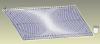
I often create my own toolpath geometry in Rhino/Grasshopper and I tend to create additional geometry to link passes together for optimal toolpath motion -- see attached image for example. It also means that don't have to click on multiple toolpath curves - the attached example is pretty mild in this regard. If I could make the linking geometry a different line type -- say dashed -- so that G00 moves would be output instead of G01, it would be an very useful feature.
-
7
-
-
Hey MIL-TFP-41 -- That did the trick. Thanks for your help
ps for those who don't know -- removing the # will uncomment the line.
-
Thanks 5th Axis -- I'll dig around and see if I can find it.
-
I downloaded the mpaster X8 post processor. Updated post, control, and machine def to X9.
Trying to use the post for a 4 axis HMC (B rotary axis).
I make the Top plane the WCS, Front plane is the Tplane --- no B axis index (should be B0.0) when i post.
However everything seems to be working fine when I change the Tplane to another plane.
In this case I do get B index moves, which is what I want:
WCS Top, with Tplane Right outputs B90.0
WCS Top, Tplane Back -- B180
WCS Top, Tplane Left -- B-90.0
Is there a way to get the post to output B0.0 ?
thanks
Bret
-
I have searched the forums on how to enable HPCC in the post, but I have only found this thread: http://www.emastercam.com/board/topic/71735-aicc-g05q1-how-to-enable/?hl=hpcc#entry834720
It is helpful, but only shows where to enable HPCC in the misc values tab from within the parameters of a given toolpath. However, I see that there is a check box on the misc values tab that says 'Automatically set to post values when posting'. Is it possible to configure the post so that HPCC will be automatically turned for all toolpaths that support it, instead of having to individually enable each toolpath?
Also, I did post out a toolpath with HPCC enabled in the misc values tab, but G05 P10000 was added after G43 -- Aren't all tool length offsets supposed to be canceled before HPCC is enabled, which would mean that g05 P10000 should go before G43?
thanks
Bret
-
Solution: I changed parameter 1404 (bit 2) from 0 to 1, this enables the control to accept feed rates of more that 999.99.
-
1
-
-
I've programmed a part with 4th axis simultaneous motion that I'm trying to run on a Kitamura HX300iF with a Fanuc 16i-mb controller. The inverse time feed rates are really big (xxxx.xx) which causes the fanuc control to throw the 003 'too many digits' alarm. As far as I can tell, the F register on the 16i-mb has a 3.2 format so anything over 999.99 is a problem. I adjusted the max inverse feed rate in the machine definition to 999.99, is that the best way to control the inverse feedrate so that it doesn't cause a problem for the control? Does anybody have experience with this type of problem on fanuc controls?
Thanks
-
I have no experience using the MP/lMaster post. This is an enhanced version of the Mpfan created by In-house-solutions? Does it provide more options to the user to modify/configure post beyond what is available in the machine/control def?
I should also add that I am using X6 for solidworks.
-
Hi -- I need to configure a post processor for a Toyoda FA550ii with a GE Fanuc Series 16i-M. This is my first time programming for a 4 axis HMC, and my reseller has suggested using the generic HMC post. Does anybody have any experience with this machine, or better, have experience configuring a post for this machine? Any help would be appreciated.
-Bret Vanderhyden
Goleta, California
Compromised Performance with Windows 10 v1709 (OS Build 16299.125)
in Industrial Forum
Posted
I recently updated Windows 10 to v1709 (OS Build 16299.125) and Mastercam 2018 MU2 has been running slower. I mainly notice the issue when opening toolpath parameter dialogs and navigating through the various tabs. When switching through tabs, it can take a few seconds for the new page to appear. I installed the latest driver for my graphics card (NVIDIA Quadro 4000) but the issue persists.