


CristiP
-
Posts
43 -
Joined
-
Last visited
Content Type
Profiles
Forums
Downloads
Store
eMastercam Wiki
Blogs
Gallery
Events
Posts posted by CristiP
-
-
8 hours ago, cncappsjames said:
That's A LOT of error.
Are you using G54.4, G68.2 and/or G43.4?
Yes I know. I don't know when the machine kinematics was checked last time as I'm not usually working on this machine. I decided to check it after a not so good cmm report. We are using G68.2 and G43.4.
Thanks
-
3 hours ago, crazy^millman said:
Where? At the machine or in the CAM? Are you programming from COR? Setting up the machine from COR?
Matsuura mam72-100h is the machine. It's a big table/table machine with all the fancy full 5 axis capabilities. There is no need to position my part in CAM the same like on the machine, the machine will handle all this. All I want is to update the machine center of rotation as my part doesn't look great and by checking the COR I find out it is out 0.018 in x, 0.023 in y and 0.036 in z. Because I'm using 240 tool on this job and I want to update the COR I was thinking if this will affect in any way other stuff I have set for this job like tool lengths.
thanks
-
Matsuura mam100 5 axis machine table/table
-
Will updating the COR affect the tool lengths?
Thank you for your time.
-
I don't know if Mastercam has this function but I know for sure Powermill does and yes it is nice to have it.
-
1 hour ago, crazy^millman said:
WCS if you main positional location for your programming. It controls your 6 Degrees of Freedom. Six Degrees of Freedom Then we get into the math behind the Post processor we start looking at Euler Angles and Matrix Math. Euler Angles Those links are those who like me read a lot technical information.
When you program in Mastercam the WCS allows you great freedom and flexibility to program as many operations that are needed from one model without the need to move the model to different orientations to machine it. On a VMC 4 Axis machine we have normally have the 4th Axis rotating around the X axis and that gives us A Axis output. In Mastercam we set the WCS to the Zero position we want to use when we setup the part in the machine. If you are thinking the very front of the part then that is where you would place the WCS at if the part is not located correctly in the Mastercam like you need. There are two schools of thought when it comes to programming in Mastercam. The first school of thought is move the model to the position and location you are machining it. The makes copies of that to a new level that will be moved and rotated. the second school of thought is you leave the model where it is and use the WCS to do that work for you. You work with one model, but use levels for your machining geometry and other things needed to machine the part. I got away from the first school of thought around the V9 days, but have used it for different reasons.
The use of the WCS is what really confuses people from what I have seen on the forum and teaching people Mastercam for almost 15 years. Everyone of us is wired differently and don't get frustrated or aggravated you're not wrapping your brain around the process yet. In Mastercam you need to get a good control over the planes Manager. I use three screens with the main Mastercam in the middle. The planes Manager to my left screen and the operations/solids manager combined to the right splitting the screen with the levels manager. I set all of my work offsets in the planes manger. Since about X7 X8 they introduced Automatic crashing to Mastercam with the useless Automatic Workoffsets if you are doing anything more that a part with four holes it in. I teach everyone set your work offsets in the planes manger. Need to change them then yes there are very easy ways to change them after they are created. The planes manager is your multiaxis control central when doing anything that is 3+1 4 Axis work or 3+2 5 Axis work. in 5 Axis operations you don't have to worry about planes since the 5 Axis operations control everything you need. In Mastercam he WCS is your TOP/TOP/TOP as the part is places on the machine and you're looking at it through the spindle of the machine for a VMC. In Mastercam the WCS is your TOP/FRONT/FRONT if you are looking at the part through the Spindle of the machine. Lets stop right here and break that down. What do you mean TOP/TOP/TOP for a VMC and TOP/FRONT/FRONT for a HMC? Which was is Z when we stand in front of the machine? Z for anyone is always Up and Down and in Mastercam Z for a base WCS is still the same. On the Vertical that seems to make perfect sense, but someone new to a Horizonal machine they think not I must make the WCS the same as the spindle and sorry that is not the way I program and the way Mastercam is setup to handle the machining environment. The FRONT/FRONT are the Construction and Tool Planes in Mastercam. They let the Post Processor know you are machining in a HMC machine and do all the heavy lifting for you when it comes to rotations and multiaxis work. We want to machine at B 90 degrees on a HMC we use the TOP/RIGHT/RIGHT we want B 1180 we use the TOP/BACK/BACK. The WCS has not changed, but the C and T planes have changed.
The VMC is not different, but we have a machine and control definition made to support our machining environment and again it does all the heavy lifting for us to work with the post to take what we need and convert it to G and M code to run on our machine. We want to machine at A90 then we use TOP/FRONT/FRONT and normally we get A90. The difference here is the Axis of rotation. on the HMC we are rotating around the Z axis so I had to sue the right plane. On the VMC we are rotating around the X axis so I have to use the Front plane. The WCS for that machining operation never changes, but the C and T planes will change for each angle and rotation I am machining if I am using planes to control those rotations. We have many ways in Mastercam to do rotations from 4 or 5 Axis drilling, Transform Rotate Toolpaths to any of the Multiaxis toolpaths. The key is the WCS is your base of operation for all toolpaths related to a setup. Need to machine the other side of the part. Then make a new WCS and name it 2nd Setup or G55 ZERO in your planes manger. Make all of your work from that and keep moving to completion. Once you stop and realizes we always use this process in our daily live from anything like typing on the key board to drinking a soda with our own bodies then we realize we have been programming our whole lives. We just don't think about all the steps needed to make those motions, but break each key type on the keyboard down to CNC code and what your fingers have to do to just type a word and you see how really smart every human is.
Share a sample part and someone can walk you through the process. The Official Mastercam Website if offering Free Mastercam U classes all you have to do is register on their Web Site to access them. In-House the providers of this Forum have a great resources along with many others out there. There is not need to struggle with so much out there we didn't have when I first got into this line of work. For the most part self taught and don't have a College degree.
Have a good day and look forward to seeing what can be done to help you progress forward.
Nice post man!!!! Pleasure to read it.
-
 1
1
-
-
You have to create and use an angle head.
-
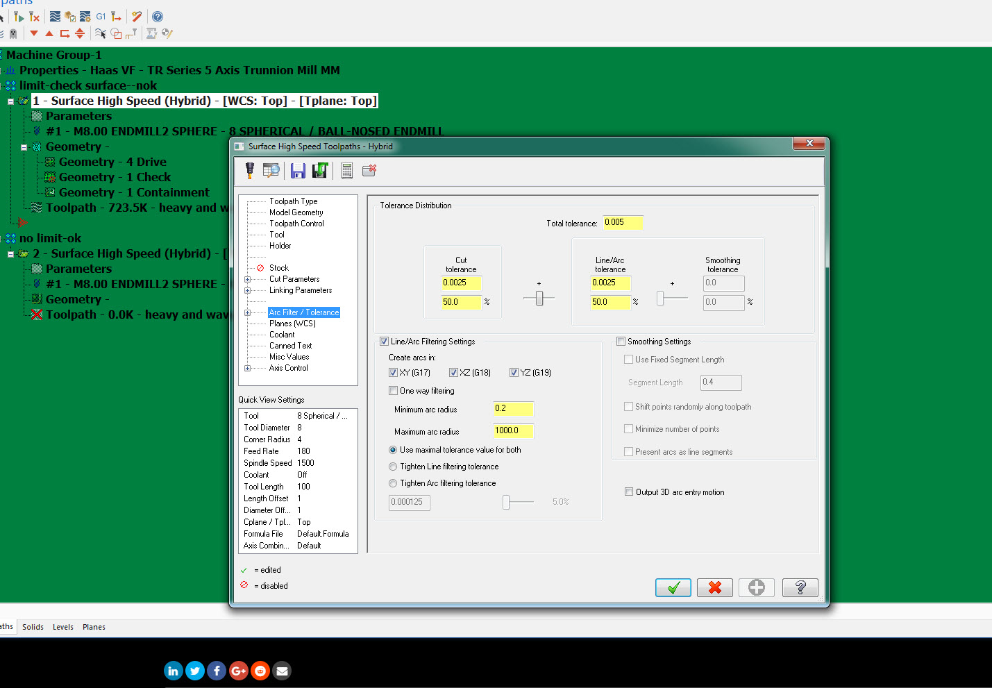
Lets you set an additional start and end margin to overcome surface edge inaccuracies.
-
Has to be done from the position the 3d model is saved, with a lollipop cutter.
-
Hello,
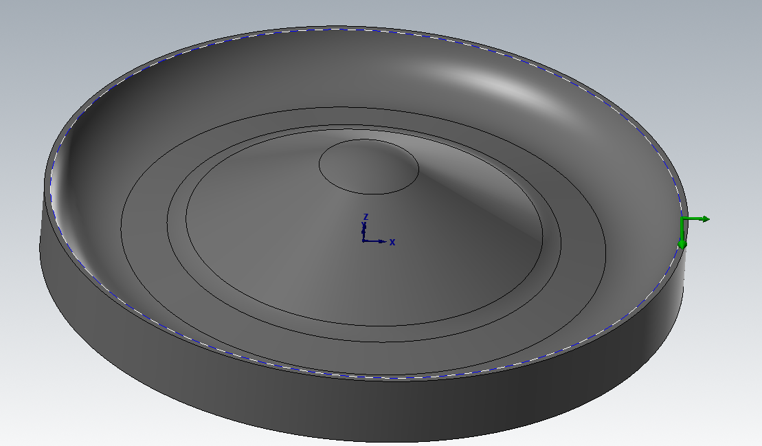
I have to deburr this holes intersection and I can't do it right. Please look at the attached dropbox link for a picture. I also attached the 3d model. I need help here, please.
Thank you very much.
https://www.dropbox.com/s/5ptwc4yhdw4w33e/PIC%201.PNG?dl=0
-
15 hours ago, pullo said:
yep , proved my point
.gif ":)") ))))
))))
Gracjan
I understand about using the right toolpath for the job and I agree with all of you, but it was just a case regarding this problem.
Thanks
-
1 hour ago, JParis said:
I offset it a different way but I dunno, looks reasonable to me
https://www.dropbox.com/s/uaqop82kfh5f8y0/JP_heavy and wavy.mcam?dl=0
thank you : ) looks good!
-
2 hours ago, Müřlıń® said:
Same hybrid tool path with a solid instead of a surface....
No fancy filtering....
Learn what makes the software tick and you will stop going in circles...


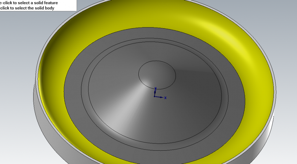
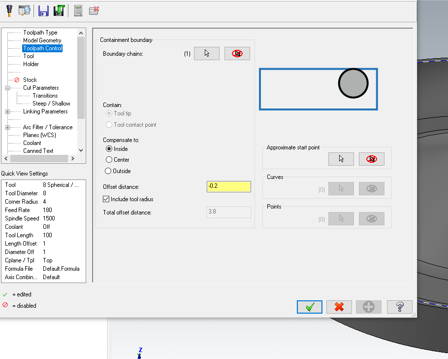
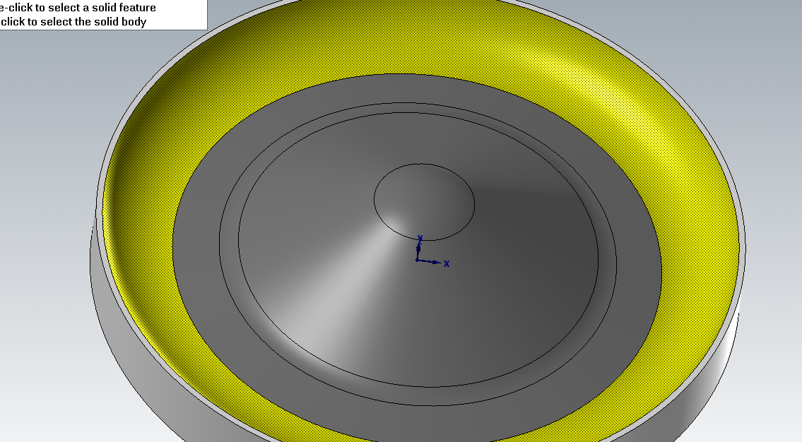
ok, but you have only 4 drive surfaces and you need 5 in order to machine all the cavity. You did not select the outer most surface, the yellow one from the below picture. If I do the same the toolpath is also ok like in your picture, but if you select a boundary and you choose stay inside -0.2 to keep the tool like in the below position you will see that your results are different.

-
recently I programmed some big parts 80% made by NURBS surfaces. "Legacy" toolpaths took a lot of time to calculate the toolpath but the HST were 70% faster.
-
2 minutes ago, pullo said:
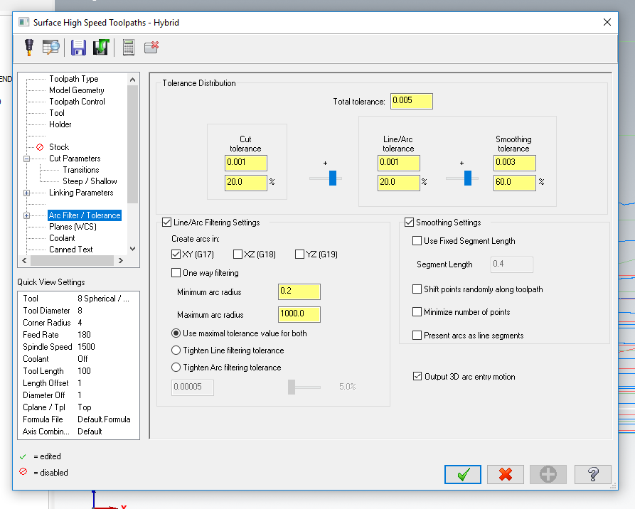
OK , so you have one of the best machines , so Z is not a problem . So I would go with Spiral , total tolerance 0.004 , for D8R4 a step of 0.12 will give you a miiror finish.
For your other machines , if you want to maintain a constant Z, thereby allowing for the creation of arcs in your NC-code , I woukld suggest the classic Contour , with shallow turned on.....

I agree. I'll try contour also with shallow turned on. Thank you very much for your help.
-
3 minutes ago, pullo said:
Pencil unlimited would be in my opinion a general solution for creating smooth toolpaths in complex topography. But since your example here is circular , it's definitely spiral the way to go in my opinion .
I would not classify my toolpaths into good/bad just by looking from the side , unless you have some problems with achieving a good finish by minimizing the change in your Z
axis. Do you have Heidehain in your machine for control ?
GRacjan
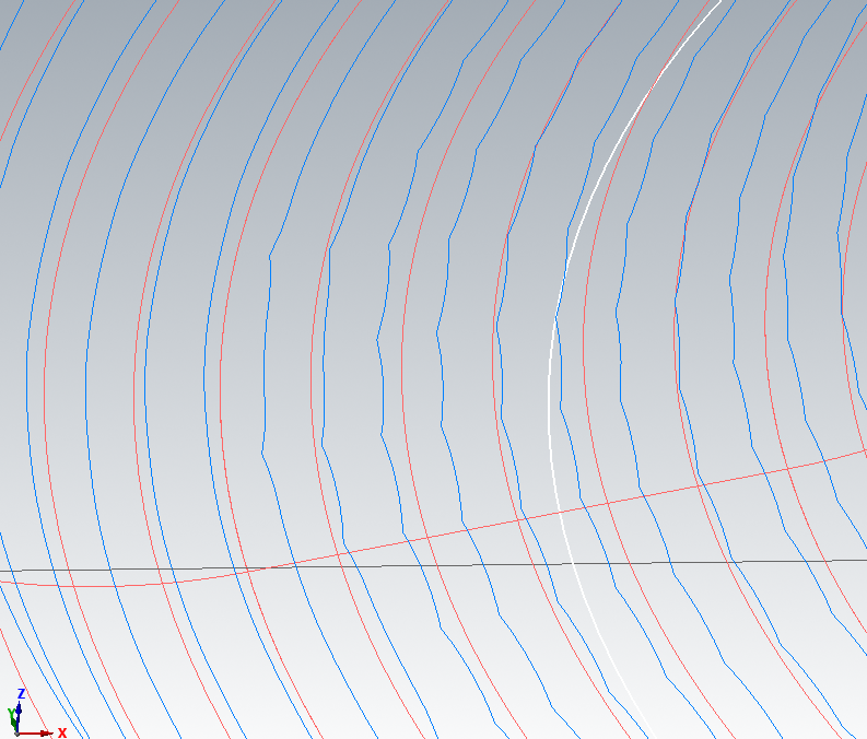
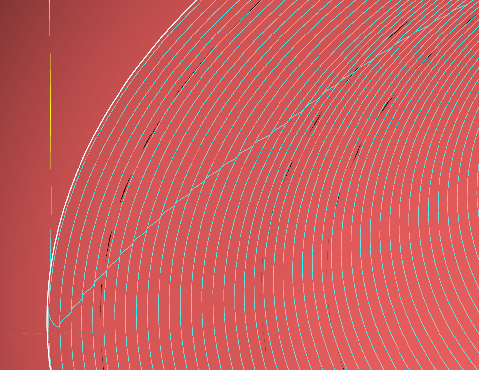
I agree the spiral it's more suitable for this part but I'm not looking for the best toolpath to make this part. It was just an example to show you those waves or Z changes along the toolpath. I have hermle C32U with heidenhain TNC640 but here there is no problem with these Z changes along the toolpath but on less expensive machines the surface finish and tool movements are serriosly affected by these kind of toolpaths. For those machines I use powermill because there I did not see these Z changes along the toolpath. I will practice more with stock to leave and tolerance to obtain a more smooth toolpath with less Z changes. Did you try it with 0.025 tolerance and stock to leave zero and then same tolerance but stock to leave 0.01? I'm not classify my toolpaths from the side view, but if this is a problem in making your machines to not work properly or to affect your surface quality...Thanks
-
15 minutes ago, Help_me said:
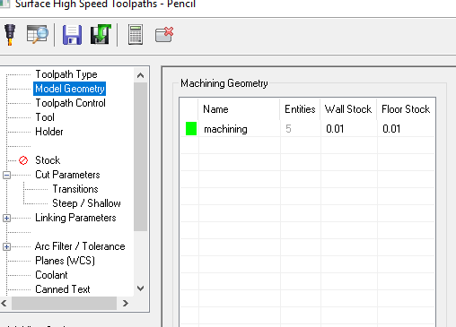
I've tried with pencil but still "wavy". I have just drive surfaces, a boundary and an overthickness of 6mm. Can you give me your mcx file please?

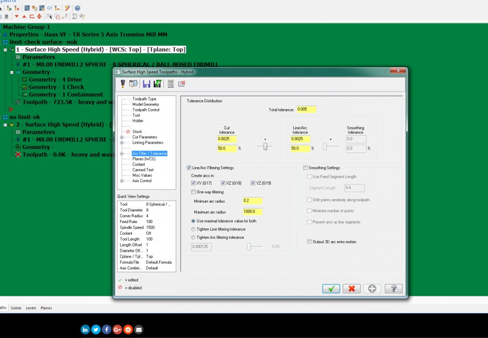
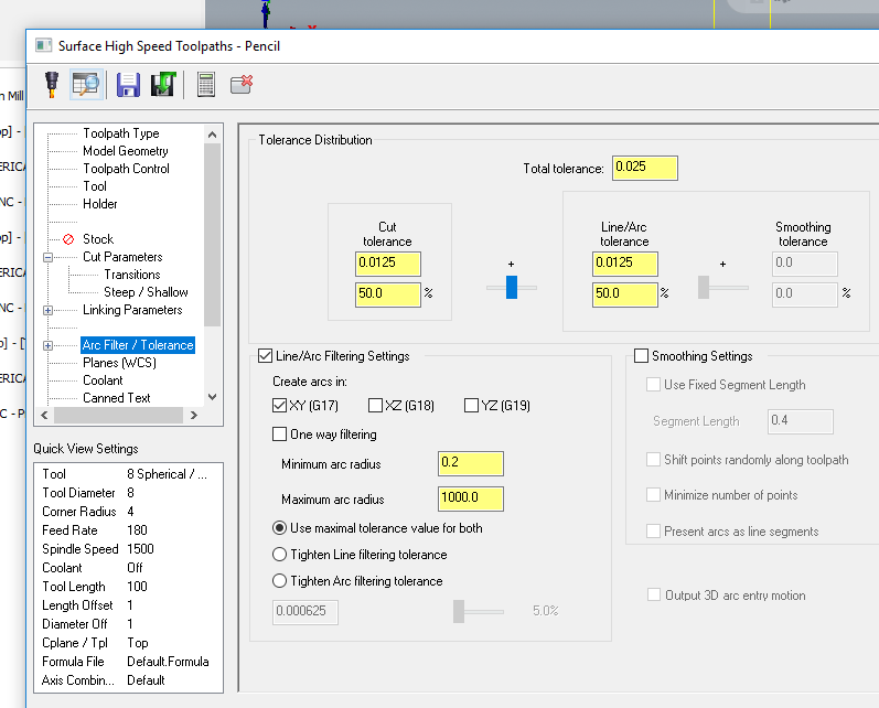
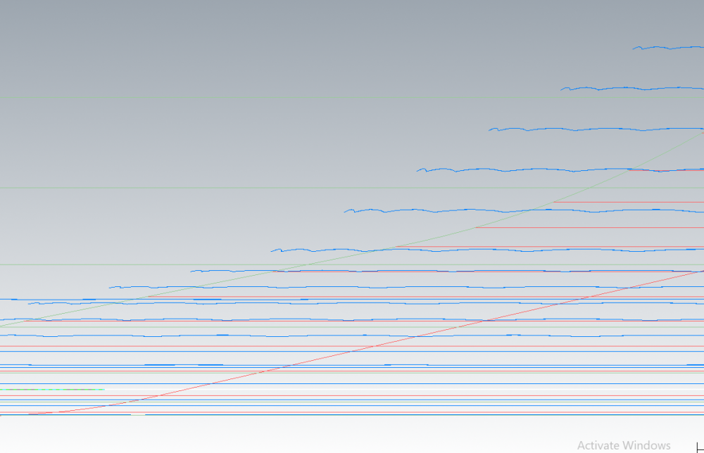
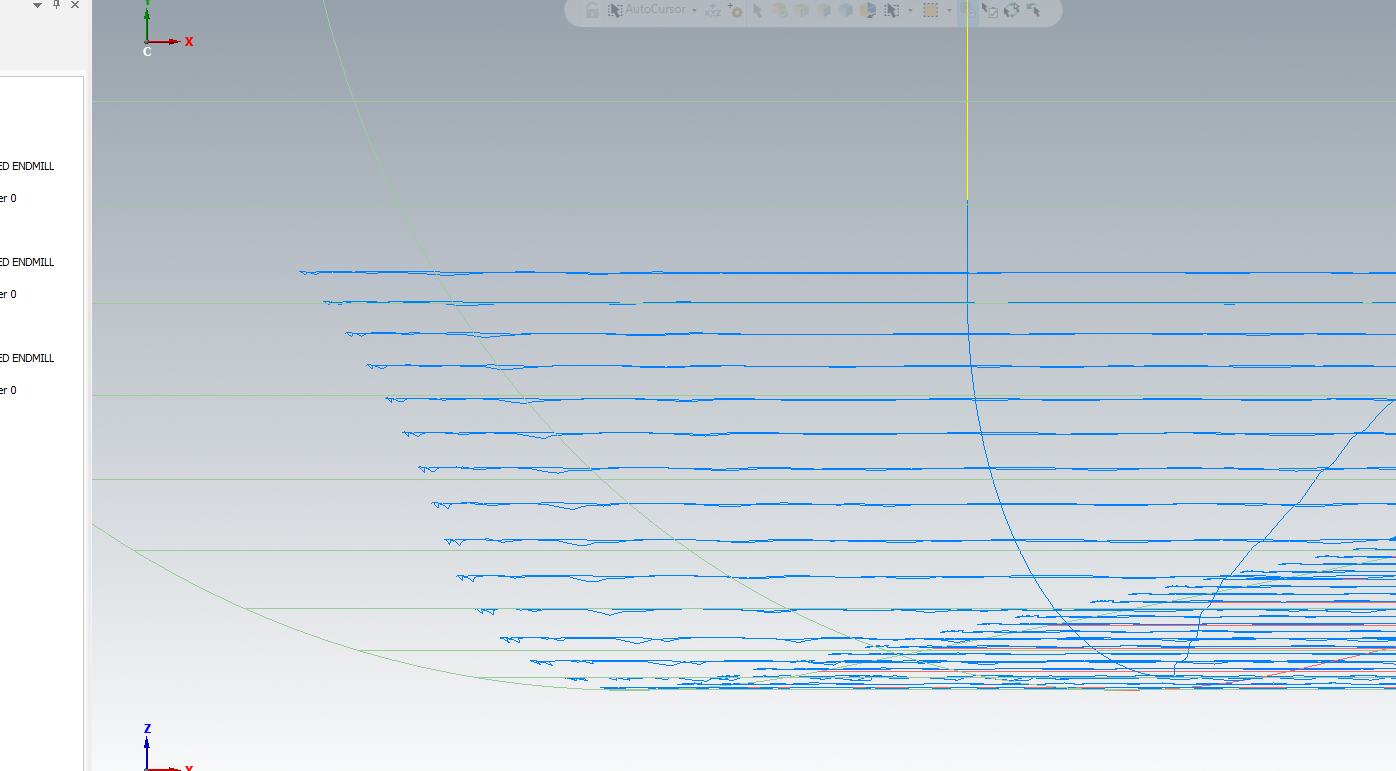
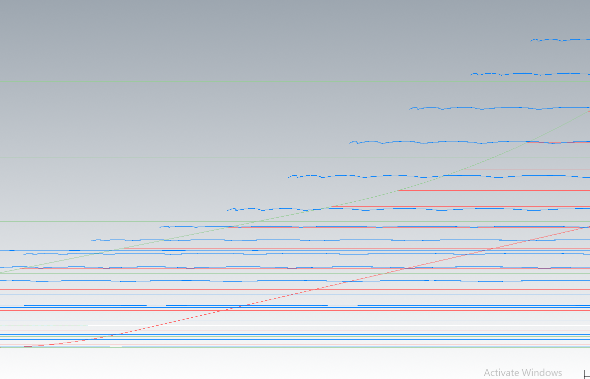
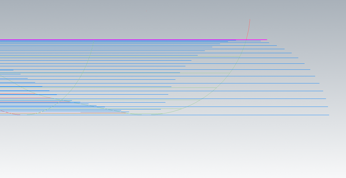
It seems that if I change the tolerance a little, thing are getting better. The above picture was calculated with a tolerance of 0.025 and a stock to leave zero. If a leave a stock of 0.01mm on the surface it is ok, no "wavy" toolpath. The trick here is to play a little with the stock to leave and the tolerance I think. For example If I left zero stock on the surface and a tolerance of 0.025 no chance......but if I change the tolerance for example 0.06 I avoid the "wavy" toolpath.
-
27 minutes ago, pullo said:
Your part (the plate looking part )is even simpler as an internal radius is inside the machining area. You must remember to force the toolpath to be made by applying the right overthickness.
I was not able to induce a toolpath creation using old school pencil, but high speed pencil with an overthickness of 6 mm gave me a nice toolpath.

However, since we are talking molds , those "wavy " cut entrances and exits will make the guy who has to polish this surface curse you till the end of time.
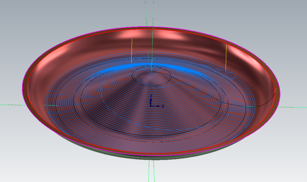
You need here a toolpath with one entry and one exit. Here the right choice is High speed spiral, especially since your part is circular.

Gracjan
I've tried with pencil but still "wavy". I have just drive surfaces, a boundary and an overthickness of 6mm. Can you give me your mcx file please?
-
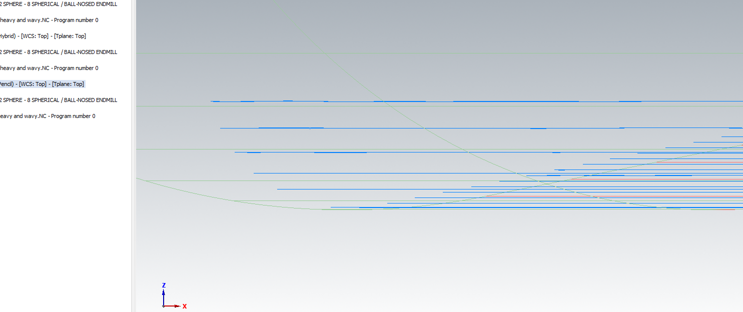
1 hour ago, pullo said:
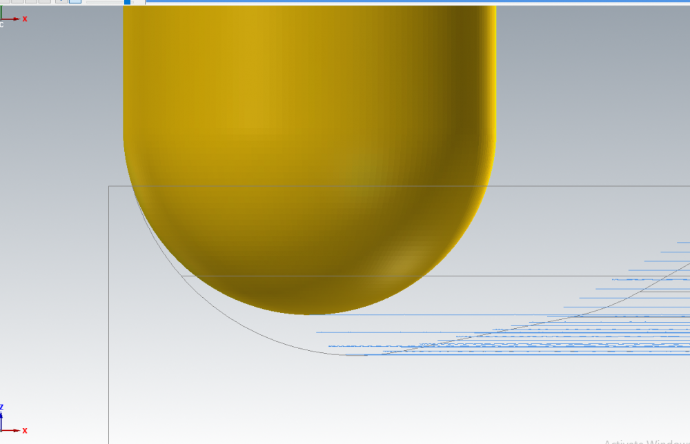
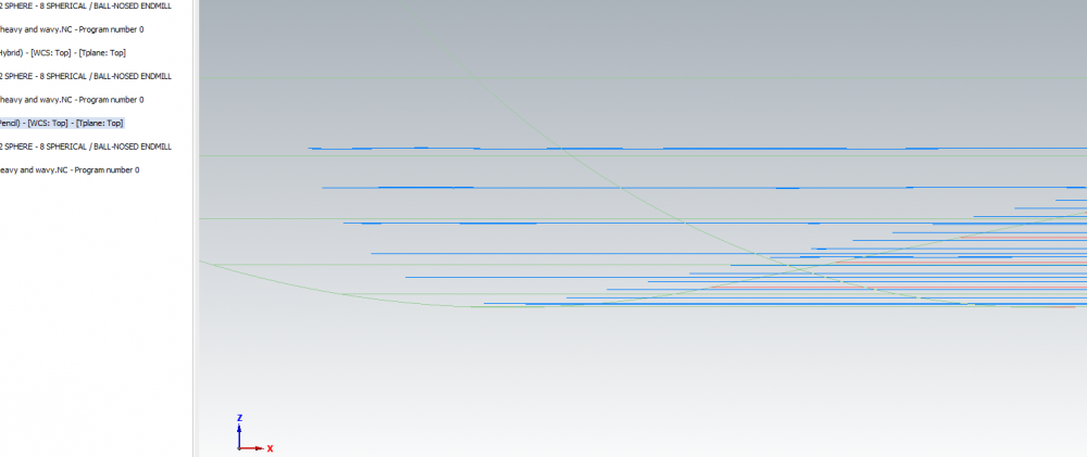
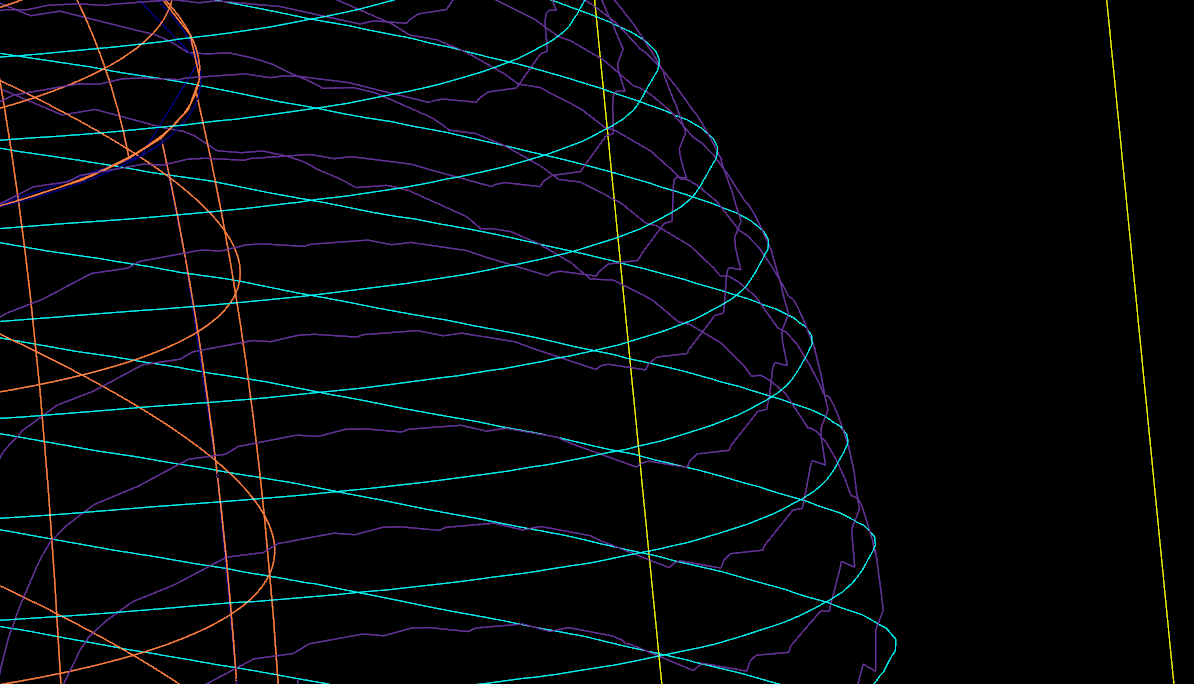
I tried hybrid , but the quality of the toolpath vs pencil leaves much to wish , cyan is pencil , purple is hybrid.
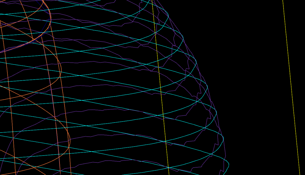
Thanks. I will try pencil to see the results. My part was the one from the below pitures but it's almost the same situation. I'll try and I'll come back with feedback. Thanks again.


-
can somebody help me with the above post regarding simple revolve part and the wavy surface high speed hybrid toolpath? I attached a mcx 2018 file to that post. I canot run such a toolpath on less expesive machines. What ingredients do I have to add to that toolpath to remove these wavy effect. Thanks
-
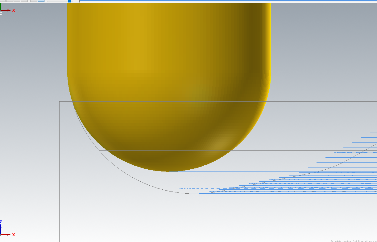
I have the same problem see attached photos and mcx 2018 attached file. If I pick a containment boundary or a check surface to limit my surface high speed hybrid toolpath or a scallop toolpath I got a wavy toolpath...If I will not use check surface or containment to limit the toolpath everything is ok and smooth. If you have a high end machine this is not important but if you have something else this wavy toolpath will be a very big problem for your part surface quality and your machine will not run smoothly. For this reason on this old machine I use another software to program my parts. Can somebody give me a tip on how to get rid of these wavy toolpaths? So why limiting my toolpath gives me these wavy thigs? I try with solids and it is the same thing..I don't want to use 5 axis toolpaths I just need 3 axis legacy toolpaths or high speed toolpaths. I saw in 2019 they add some projected boundary smoothing tolerance for equal scallop toolpath, but I'm interested on x8 and 2018 to solve this.
Thank you very much for your time.


-
you can use a contour toolpath with axis substitution to see if this is acting the same way as your project curves toolpath
-
With MC2018 it is possible, but you can use old 3d toolpath if you do not have 2018.
-
 1
1
-
-
maibe you can use Highfeed function...is next to G1 --post operations,


Center of rotation
in Industrial Forum
Posted
I uploaded 2 pictures. One is with the old #19700's and one is with the error I've found. To the old #19700's parameter I added the errors
#564 to X, #565 to Y and #566 to Z
I don't know from where are the errors. Yesterday I updated the COR and this morning after warming up the machine for 1h I've checked the COR again and they were no bigger than 0.003mm.
The only thing I know is something about the machine being leveled at the begining of the year. This was done by Matsuura and I think they adjusted the COR after that...because the only thing I did now to update the COR is probing the artefact. Matsuura machines they have an artefact you can probe to track the machine movement and of course easy update the COR numbers.
This artefact must be in relation to COR and I hope it is. I uploaded also a picture with some information related to the artefact.
Thanks