CristiP
-
Posts
43 -
Joined
-
Last visited
Content Type
Profiles
Forums
Downloads
Store
eMastercam Wiki
Blogs
Gallery
Events
Everything posted by CristiP
-
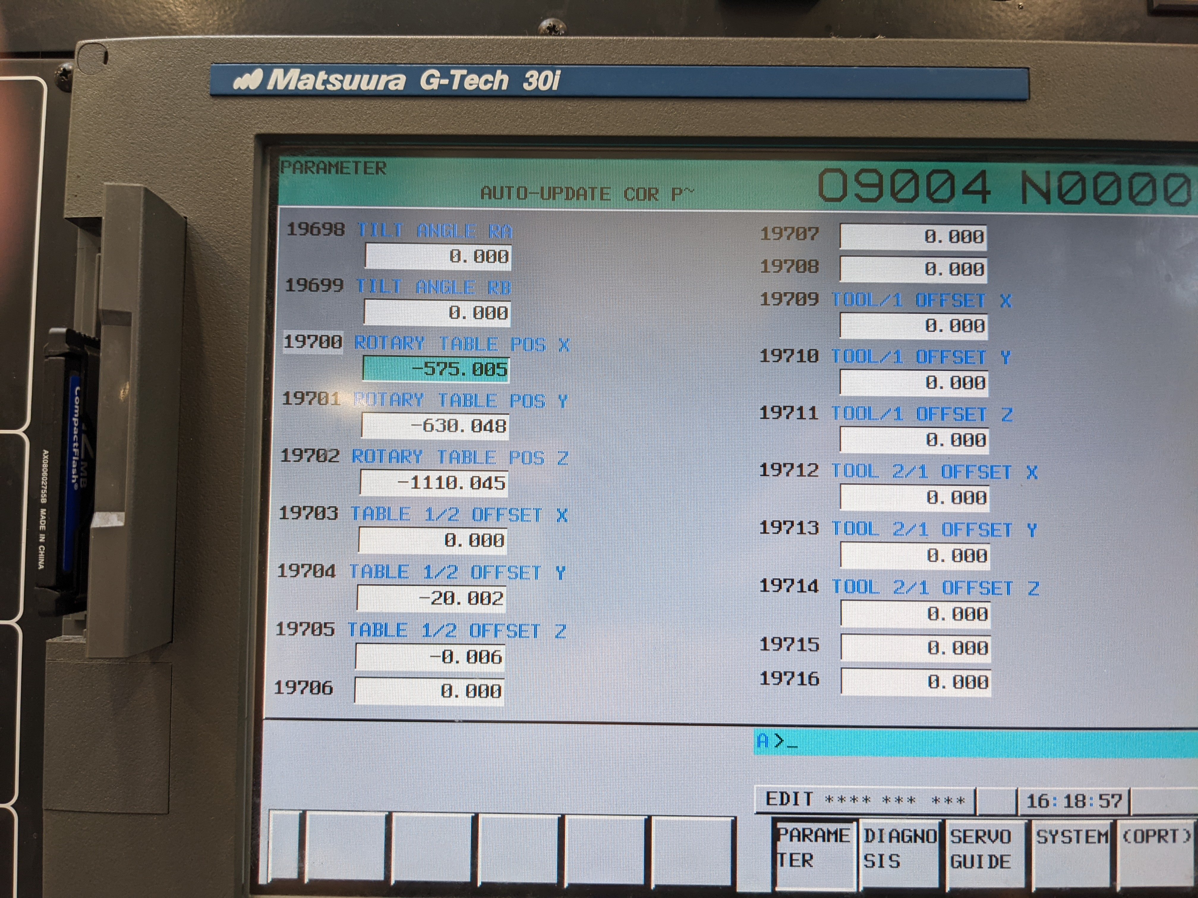
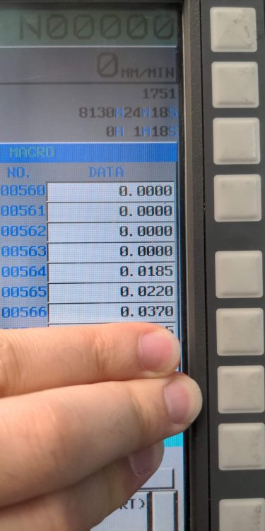
I uploaded 2 pictures. One is with the old #19700's and one is with the error I've found. To the old #19700's parameter I added the errors #564 to X, #565 to Y and #566 to Z I don't know from where are the errors. Yesterday I updated the COR and this morning after warming up the machine for 1h I've checked the COR again and they were no bigger than 0.003mm. The only thing I know is something about the machine being leveled at the begining of the year. This was done by Matsuura and I think they adjusted the COR after that...because the only thing I did now to update the COR is probing the artefact. Matsuura machines they have an artefact you can probe to track the machine movement and of course easy update the COR numbers. This artefact must be in relation to COR and I hope it is. I uploaded also a picture with some information related to the artefact. Thanks


-
Yes I know. I don't know when the machine kinematics was checked last time as I'm not usually working on this machine. I decided to check it after a not so good cmm report. We are using G68.2 and G43.4. Thanks
-
-
Matsuura mam100 5 axis machine table/table
-
Will updating the COR affect the tool lengths? Thank you for your time.
-
I don't know if Mastercam has this function but I know for sure Powermill does and yes it is nice to have it.
-

2018 4 axis a simple round part Machine on 3 sides 90 deg rotation
CristiP replied to progaseng's topic in Industrial Forum
Nice post man!!!! Pleasure to read it. -
You have to create and use an angle head.
-
Lets you set an additional start and end margin to overcome surface edge inaccuracies.
-
Has to be done from the position the 3d model is saved, with a lollipop cutter.
-
Hello, I have to deburr this holes intersection and I can't do it right. Please look at the attached dropbox link for a picture. I also attached the 3d model. I need help here, please. Thank you very much. tesire 3d.STEP https://www.dropbox.com/s/5ptwc4yhdw4w33e/PIC%201.PNG?dl=0
-
I understand about using the right toolpath for the job and I agree with all of you, but it was just a case regarding this problem. Thanks
-
thank you : ) looks good!
-
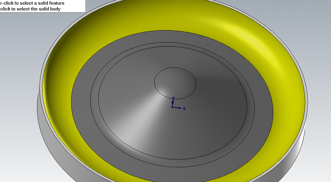
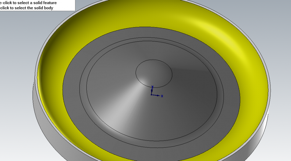
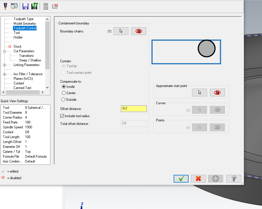
ok, but you have only 4 drive surfaces and you need 5 in order to machine all the cavity. You did not select the outer most surface, the yellow one from the below picture. If I do the same the toolpath is also ok like in your picture, but if you select a boundary and you choose stay inside -0.2 to keep the tool like in the below position you will see that your results are different.

-
recently I programmed some big parts 80% made by NURBS surfaces. "Legacy" toolpaths took a lot of time to calculate the toolpath but the HST were 70% faster.
-
I agree. I'll try contour also with shallow turned on. Thank you very much for your help.
-
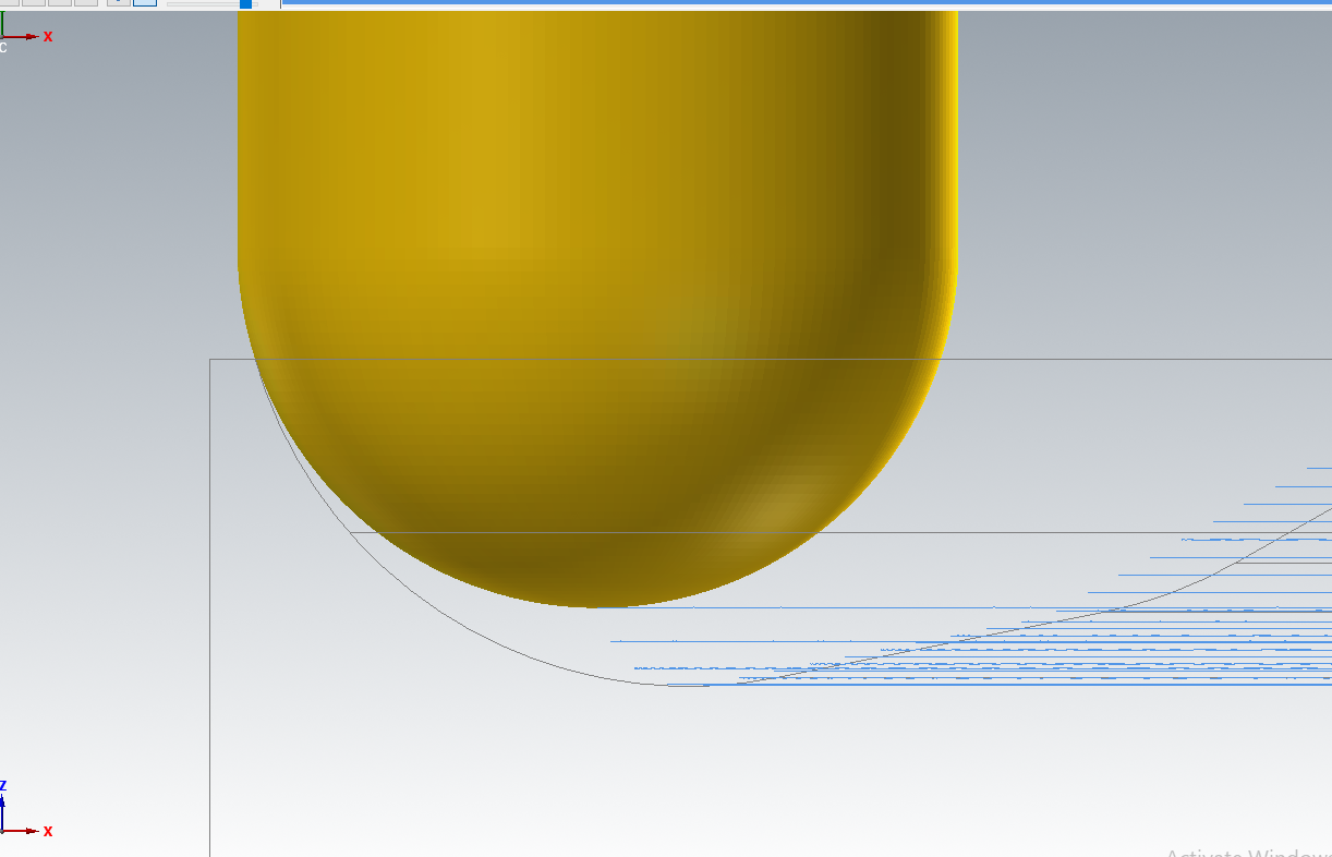
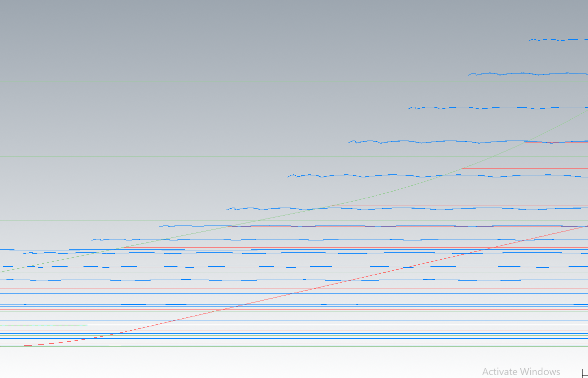
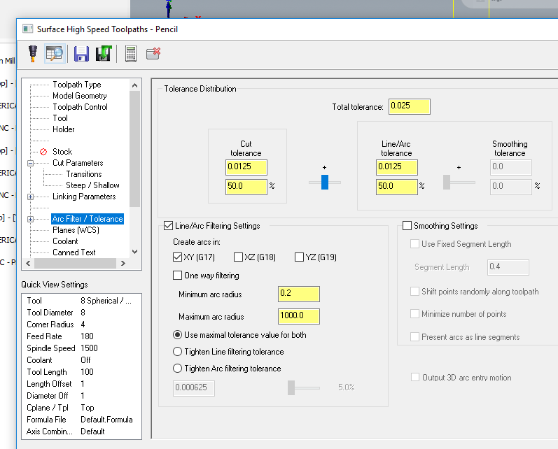
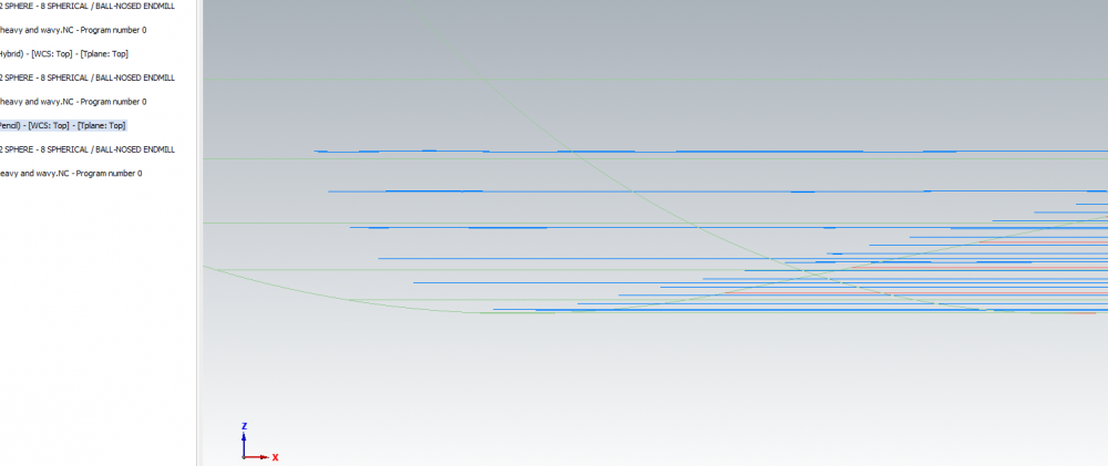
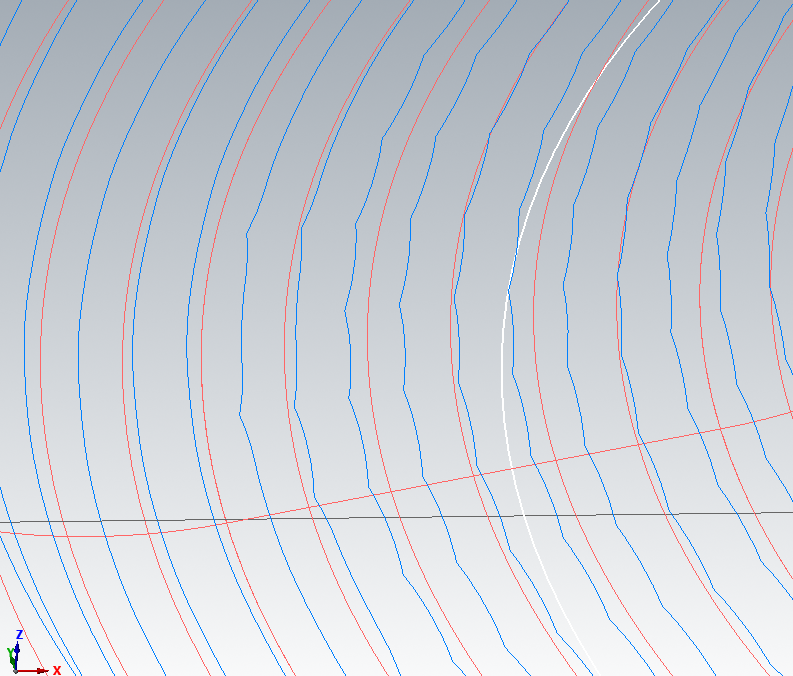
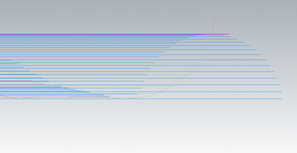
I agree the spiral it's more suitable for this part but I'm not looking for the best toolpath to make this part. It was just an example to show you those waves or Z changes along the toolpath. I have hermle C32U with heidenhain TNC640 but here there is no problem with these Z changes along the toolpath but on less expensive machines the surface finish and tool movements are serriosly affected by these kind of toolpaths. For those machines I use powermill because there I did not see these Z changes along the toolpath. I will practice more with stock to leave and tolerance to obtain a more smooth toolpath with less Z changes. Did you try it with 0.025 tolerance and stock to leave zero and then same tolerance but stock to leave 0.01? I'm not classify my toolpaths from the side view, but if this is a problem in making your machines to not work properly or to affect your surface quality...Thanks
-
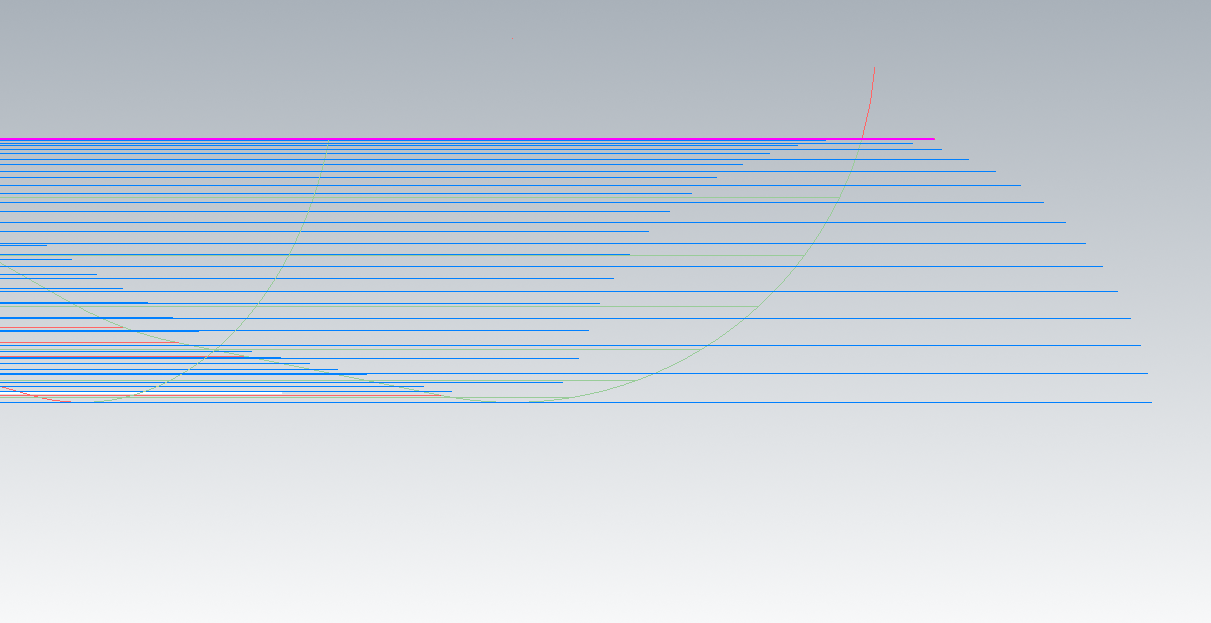
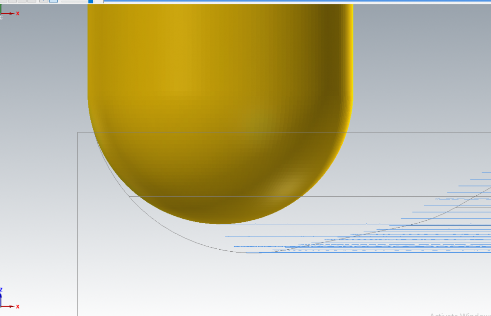
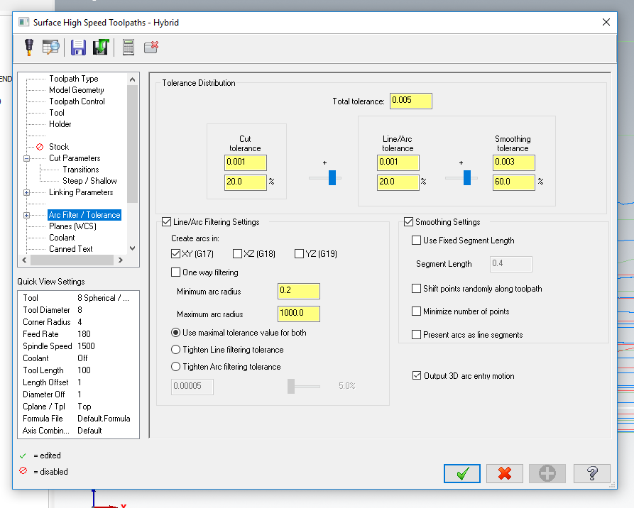
It seems that if I change the tolerance a little, thing are getting better. The above picture was calculated with a tolerance of 0.025 and a stock to leave zero. If a leave a stock of 0.01mm on the surface it is ok, no "wavy" toolpath. The trick here is to play a little with the stock to leave and the tolerance I think. For example If I left zero stock on the surface and a tolerance of 0.025 no chance......but if I change the tolerance for example 0.06 I avoid the "wavy" toolpath.

-
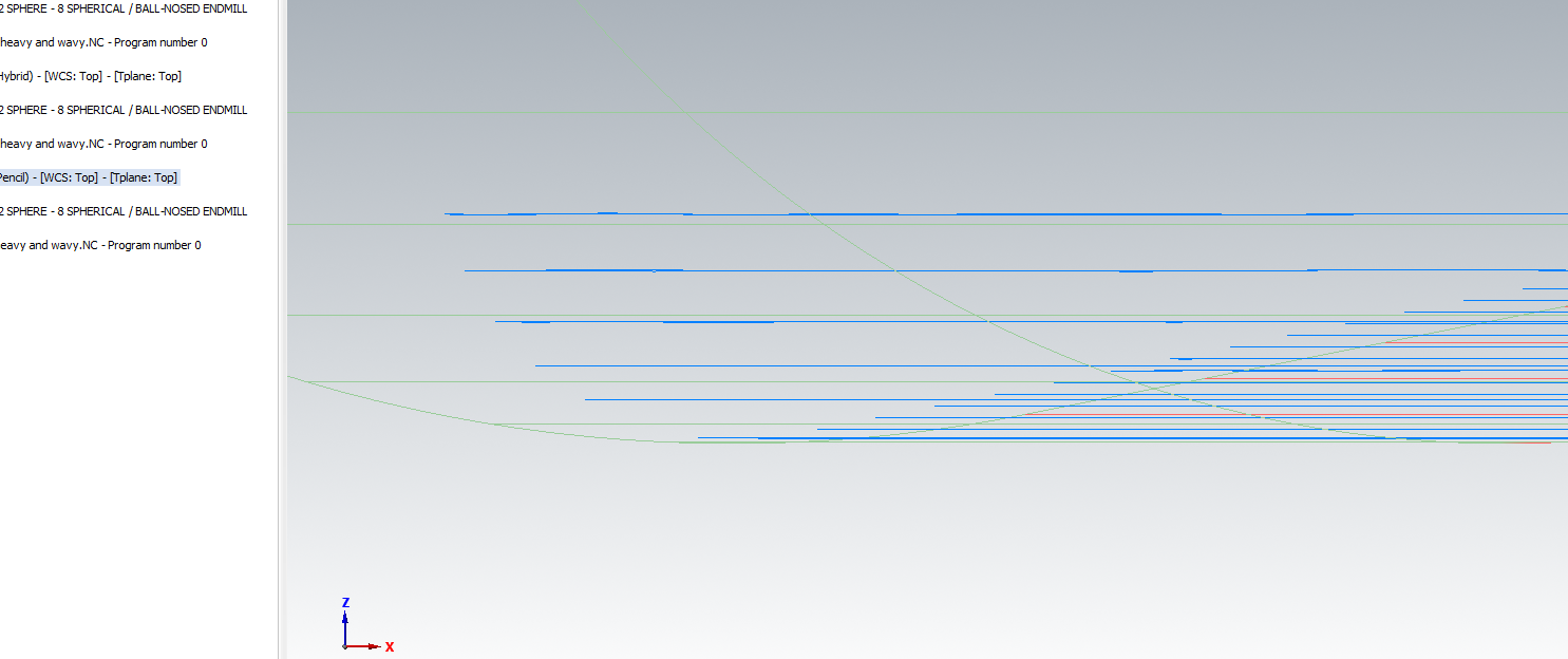
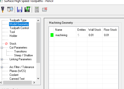
I've tried with pencil but still "wavy". I have just drive surfaces, a boundary and an overthickness of 6mm. Can you give me your mcx file please?
-
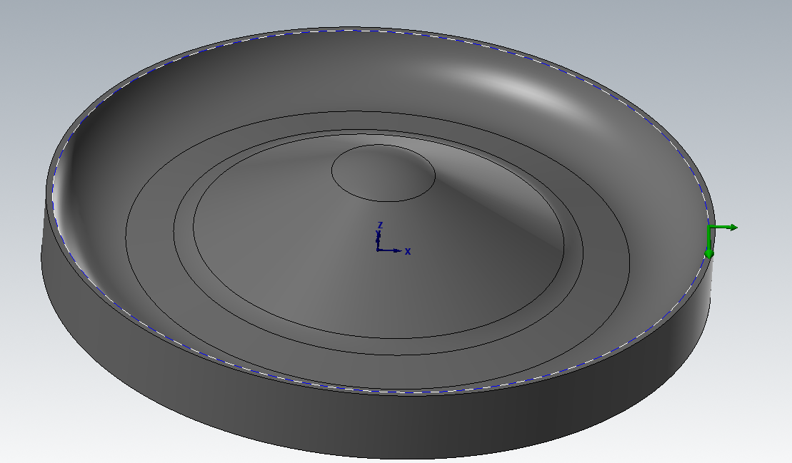
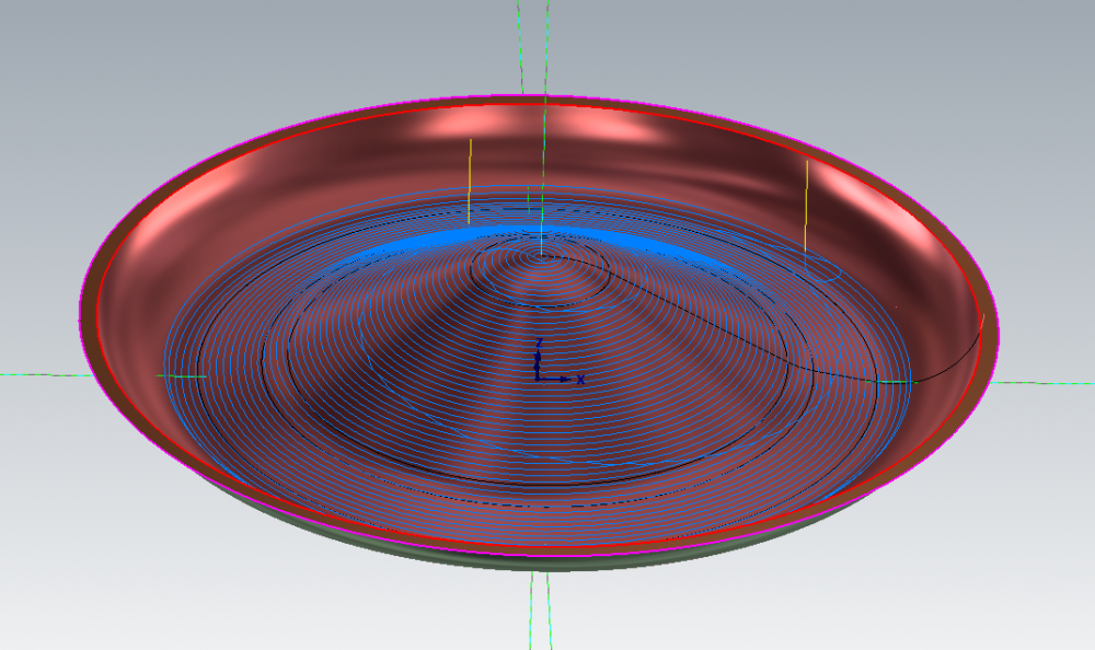
Thanks. I will try pencil to see the results. My part was the one from the below pitures but it's almost the same situation. I'll try and I'll come back with feedback. Thanks again.


-
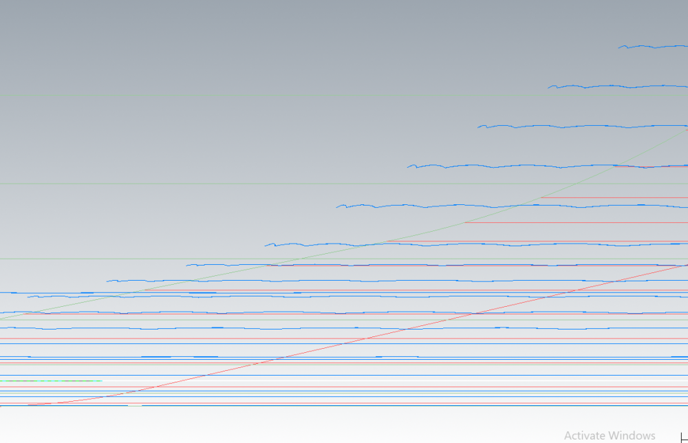
can somebody help me with the above post regarding simple revolve part and the wavy surface high speed hybrid toolpath? I attached a mcx 2018 file to that post. I canot run such a toolpath on less expesive machines. What ingredients do I have to add to that toolpath to remove these wavy effect. Thanks
-
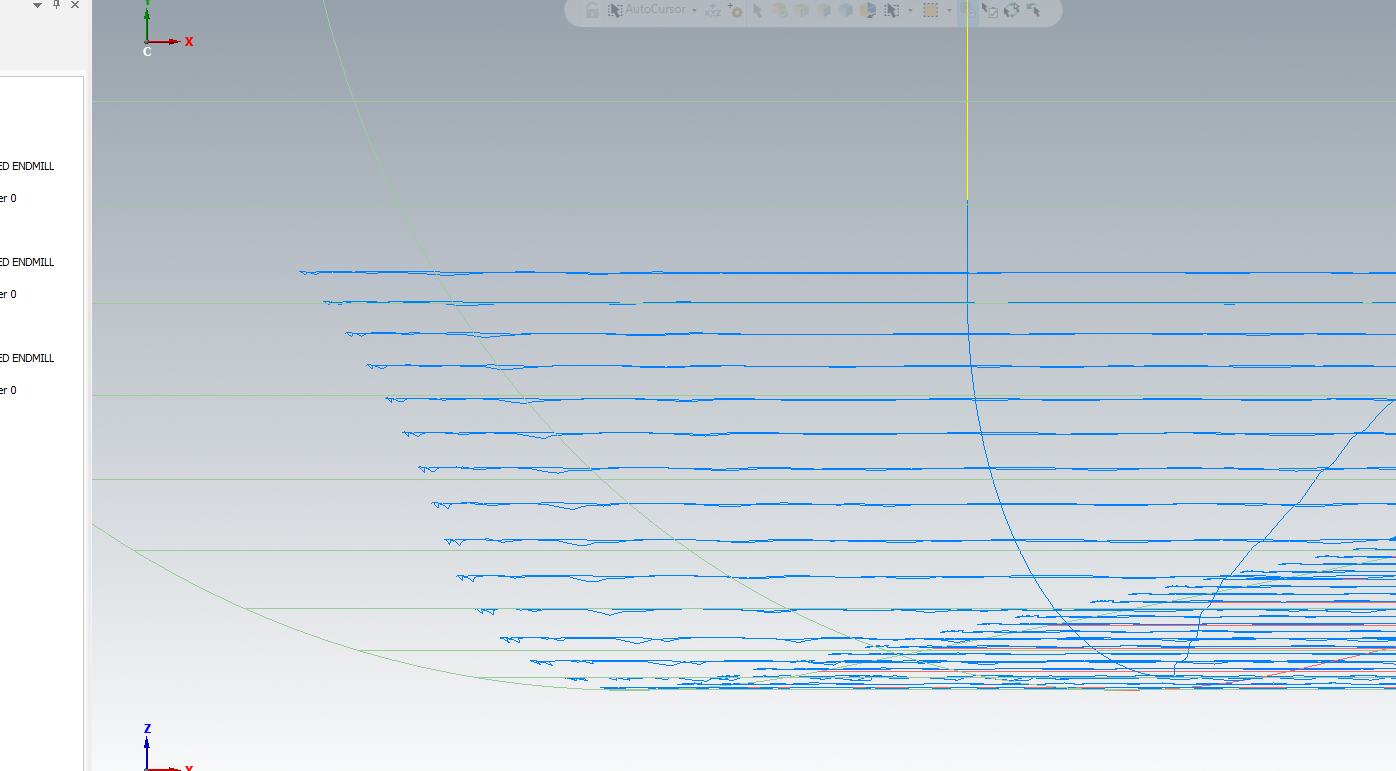
I have the same problem see attached photos and mcx 2018 attached file. If I pick a containment boundary or a check surface to limit my surface high speed hybrid toolpath or a scallop toolpath I got a wavy toolpath...If I will not use check surface or containment to limit the toolpath everything is ok and smooth. If you have a high end machine this is not important but if you have something else this wavy toolpath will be a very big problem for your part surface quality and your machine will not run smoothly. For this reason on this old machine I use another software to program my parts. Can somebody give me a tip on how to get rid of these wavy toolpaths? So why limiting my toolpath gives me these wavy thigs? I try with solids and it is the same thing..I don't want to use 5 axis toolpaths I just need 3 axis legacy toolpaths or high speed toolpaths. I saw in 2019 they add some projected boundary smoothing tolerance for equal scallop toolpath, but I'm interested on x8 and 2018 to solve this. Thank you very much for your time. heavy and wavy.mcam


-
you can use a contour toolpath with axis substitution to see if this is acting the same way as your project curves toolpath
-
With MC2018 it is possible, but you can use old 3d toolpath if you do not have 2018.
-
maibe you can use Highfeed function...is next to G1 --post operations,