


Chally72
-
Posts
499 -
Joined
-
Last visited
-
Days Won
32
Content Type
Profiles
Forums
Downloads
Store
eMastercam Wiki
Blogs
Gallery
Events
Posts posted by Chally72
-
-
3 minutes ago, Seedy steve said:
I just have growing pains trying to function in a changed workspace .
not saying a lot of stuff aint better. only tough to get through because I used V9 until a few years ago. then took a break

been on 2017/18 for a couple months now.
A decade and a half change in software version will put just about anyone behind the curve for a good while.
-
Just devil's advocate- the previous behavior was not 'actual' behavior and you wouldn't actually see if you were pecking multiple times or pecking once and then drilling to depth.
-
 1
1
-
-
No, the way that button works is, if you click 'Save', it will save out whatever is currently displayed in backplot as geometry. So, if you pulled your backplot timeline slider halfway through the op and hit save, it saves out the displayed first half of the op as lines/arcs/etc onto a level. It's not a modal button that stays on- you just have the option to save off what is displayed whenever you want, every time you go into backplot.
There are some really neat 5axis tricks you can do with this button and combining it with the use of 'restrict drawing' buttons in backplot, and displaying vector lines through the backplot interface, that let you create very slick "From" drive splines for 5axis paths, for example.
-
 1
1
-
1
-
-
Yes, there has been a change for update 3. Many people considered the previous behavior as not ideal.
-
I'm sure you know this, but GTX cards function differently than Quadro cards and are technically not supported, and a 1050 is a low end GTX card... I'm sorry I can't be of more help.
-
What GTX card and what driver version are you running?
-
Are you referring to the current ability to click and drag in the Divide command and 'swipe' over the elements you want to divide? That's what I would call 'freehand' use of the command.
-
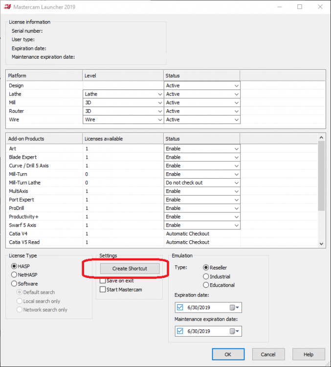
For those who don't remember the configuration switches or aren't as familiar with modifying the shortcuts, there's also the Mastercam Launcher, where you can configure the launch settings to the license configuration you want, and then create a shortcut on your desktop with this configuration.
Search Mastercam Launcher from your start bar or look here (for 2019):
C:\ProgramData\Microsoft\Windows\Start Menu\Programs\Mastercam 2019\Utilities\
-
1
-
3
-
-
That's a ~19mb .dll file located exactly where the message says. It is necessary to run verify/machine sim. Check your recycle bin and search for MachSim.dll and see if you can find it- it was deleted or moved somehow.
-
1
-
-
15 hours ago, So not a Guru said:
What are those icons for? I've never used them.
You can use them to quickly toggle your view state between different wireframe/shaded selections. IE- shaded with contrasting edges, shaded with no edges, translucent, etc.
-
The integrated graphics card will have major issues with tool graphics and the standalone tool manager. Once you get a standalone card, you need to be sure to point the tool manager to the standalone card. See here:
-
On 10/23/2018 at 6:46 AM, The Chipmaker said:
I can't get the DXF way to work , but I can create them in the stand alone. The problem I have is how do you assign the holder in tool manager? I can merge them in on a level and use that, but I want to assign them thru the tool manager. Good luck everyone.
Click the assembly button on the ribbon in the standalone tool manager. This creates a new tool assembly. You can see the assembly tree now down in the bottom left. Then, go to your holder library, and drag a holder onto the assembly tree. Then drag a tool from your tool library onto the assembly tree. You now have a holder/tool as an assembly, and if you open this library in Mastercam, it will show as an assembly. (See radio button options on lower right half of Mastercam tool manager in a file to filter between just tools, tools with holders (assemblies), or both.)
To set projection (stickout) of an assembly in the standalone tool manager, hover over the holder in the graphics display. When you see the little up/triangle icon appear, hold Ctrl and click on the holder, and then you can drag around and set tool projection. This way, this is all set up in your library when you load it into a file- no screwing around with holders and projection distances when you first start creating operations.
-
1
-
-
When you say you have to move the dialog from screen to screen, is the behavior such that it always works on one monitor, but not the other? Or that dragging it across screens, doesn't matter which way, changes the dialog visibility?
-
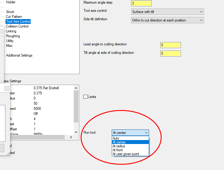
Also, even with a standard tool definition, remember that there is the Run Tool dropdown in the Tool Axis Control that can still cause you to run to the center of the tip instead of compensating to the edge you want. See image below.
-
This is a known bug. Sometimes playing with the Z stepdown can remove the double cutting. Equal Scallop is a good alternative while waiting for the fix.
-
That would vary wildly by tool. I always skip over HSS and use cobalt. Just as a guess, your SFM might be too high for HSS. I go all the way down to 18SFM in some stainless parts to get the best drill life and hole quality on low quantity parts. Also, don't drop down to a 0.1" peck until you're deeper in the hole. Only peck when you need to in order to eke more life out of that drill!
-
Yes, this would be a custom cycle, as Haas G83 peck drilling only supports a dwell on the last peck. If it's only a few holes, just do a normal G82 drill cycle with a dwell, and copy and paste the operation a few times and set the depths successively deeper. Then at least you can try the dwell at each peck without writing out a long form cycle. By the way, I have read the same thread you posted and used the knowledge within for stainless and Inconel. It helps. I was doing more damage with IPT feeds too slow than I was with not having a dwell- just some advice.
Another tip for saving the tip, if you will, in stainless- use a 142° spot drill and not a center drill to spot the hole location! Too few people do this.
-
Under the Cut Parameters | Steep/Shallow tab, you just need to uncheck "Use boundaries as machining curves, then collapse." This will keep it from jumping back and forth trying to machine the bottom opening loop and the upper areas as it works its way in.
-
1
-
2
-
-
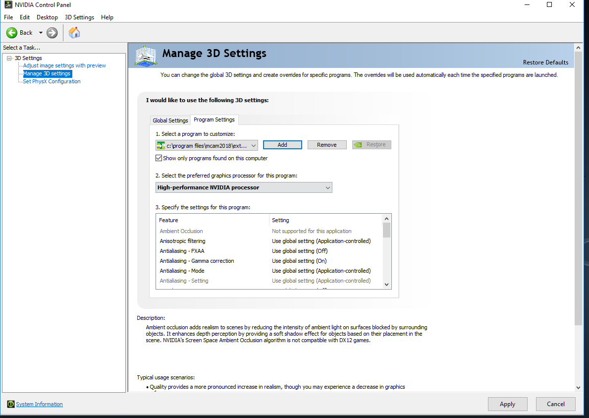
I have seen this issue occur on laptops with integrated graphics. The Tool Manager, for whatever reason, tries to use the Intel integrated graphics first, and when it needs to draw something on the screen, like when you double click on Cutting Tools or Holders after opening a library, it instantly locks up. I went up and down driver revisions for the Intel integrated graphics on my laptop and couldn't solve the issue that way.
The solution is to force the use of your dedicated graphics card for the Tool Manager application. This applies to desktops with integrated graphics as well- This is the process for NVIDIA cards:
1. Right click on the desktop and choose Nvidia Control Panel.
2. Go to Manage 3D Settings on the lefthand side.
3. Choose the Program Settings tab on the right.
4. Select Add under "Select a program to customize", and navigate to the location of your tool manager. By default for 2018, that is C:\Program Files\Mcam2018\Extensions\ToolManager.exe
5. Under "Select the preferred graphics processor for this program:", select High-Performance NVIDIA processor to force Tool Manager to open with the NVIDIA card and skip the Intel integrated graphics.
6. Hit apply in the bottom right corner. Repeat these steps for any other installed versions of Mastercam to ensure each tool manager version works with the dedicated card. You should now immediately be able to open up the tool manager and view libraries without crashes.
See the attached image for reference

-
1
-
5
-

setting spot drill depth by chamfer dia
in Industrial Forum
Posted
This is a simple way to speed 1st piece setup and prevent scrap. Either calculate and comp to the theo tip one time when you put the tool in, or touch off the tool flat and then constantly be adjusting depths per program, creeping up on chamfer size, etc, and introduce the risk of scrap.