


Cory M. Pio
-
Posts
55 -
Joined
-
Last visited
Content Type
Profiles
Forums
Downloads
Store
eMastercam Wiki
Blogs
Gallery
Events
Posts posted by Cory M. Pio
-
-
Don't do it. Don't do it. Let me see if I can make myself clear don't do it. Whoever didn't cover the tooling needed for the job needs to call the customer and add that cost to the job or give it back to the customer. That port is extremely hard to mimic and is best done with the correct tool. Any failure of the port will become the responsibility of your company. If this is going into a flight application and the aircraft crashes and they trace the damage back to the failed port your company made because they cheaped out and didn't get the correct tool your company and the supervisor who approved it will be liable. If it is R&D part and your company has to assume no responsibility for any issue that might arise from the port not being to the correct specifications laid out by the standard them by all means surface machine it, but really consider getting the correct tool for the job and do it the right way.
yeah i figured something like this...
i already bought the tool because this is a test lot and we probably get more.
-
 1
1
-
-
Never tried......if it was a standard port, there was a tool available some where
yeah,
just figured someone out there might be doing it for 5 pc. orders to save on tooling.
-
I use porting tools when presented with this feature
No guess no luck than
-
Howdy,
Has anyone ever had luck Surfacing O-RIng Ports? AS5202

-
You will go a long way sir a long way.
 :unworthy:
 i just find it CRAZY that isn't defualt for fanuc
-
fs2 4 1 0 1 0 #Integer, not leading
fmt "P" 4 dwell$ #Dwell
-
1
-
-
Awesome and thank you. I really appreciate you understanding I am not trying to be mean.
dont worry im in a safe space.
-
1
-
-
Look for dwell$ in the drilling section of the post. Then you will see the drilling cycles and how it is called from there to be output. Tne go back to the fmt statement and you will see where in this post it is using 11. Change to what is on the list and see if it will you wrap your brain around fmt statements and how they work in Mastercam's MP language.
# --------------------------------------------------------------------------
# Format statements - n=nonmodal, l=leading, t=trailing, i=inc, d=delta
# --------------------------------------------------------------------------
#Default english/metric position format statements
fs2 1   0.7 0.6      #Decimal, absolute, 7 place, default for initialize (
fs2 2   0.4 0.3      #Decimal, absolute, 4/3 place
fs2 3   0.4 0.3d     #Decimal, delta, 4/3 place
#Common format statements
fs2 4   1 0 1 0      #Integer, not leading
fs2 5   2 0 2 0l     #Integer, force two leading
fs2 6   3 0 3 0l     #Integer, force three leading
fs2 7   4 0 4 0l     #Integer, force four leading
fs2 9   0.1 0.1      #Decimal, absolute, 1 place
fs2 10  0.2 0.2      #Decimal, absolute, 2 place
fs2 11  0.3 0.3      #Decimal, absolute, 3 place
fs2 12  0.4 0.4      #Decimal, absolute, 4 place
fs2 13  0.5 0.5      #Decimal, absolute, 5 place
fs2 14  0.3 0.3d     #Decimal, delta, 3 place
fs2 15  0.2 0.1      #Decimal, absolute, 2/1 place (feedrate)
fs2 16  1 0 1 0n     #Integer, forced output
fs2 17  0.2 0.3      #Decimal, absolute, 2/3 place (tapping feedrate)

# These formats used for 'Date' & 'Time'
fs2 18  2.2 2.2lt    #Decimal, force two leading & two trailing (time2)
fs2 19  2 0 2 0t     #Integer, force trailing                   (hour)
fs2 20  0 2 0 2lt    #Integer, force leading & trailing         (min)

# This format statement is used for sequence number output
# Number of places output is determined by value for "Increment Sequence Number" in CD
# Max depth to the right of the decimal point is set in the fs statement below
fs2 21  0^7 0^7      #Decimal, 7 place, omit decimal if integer value
Yes I could give you the answer, but I want to teach you to fish for yourself verses giving you the fish.
I can dig it.
-
How do i change the dwell in my drill cycle to out P1000 with no decimal point.
I take it I have to use a Format Statement , somehow, to get this to work, or possibly not.
I read some of the post documentation but it just left me dazed and confused.
Attached is my post...#CMPEDIT are all my changes so far...I'm dowloading MPMASTER now to see if they have a switch built-in.
Forgive my terrible lack of programming knowledge I am learning slowly.
-
Program check is something i only ever used in memory mode. When i hit check during a cycle it allows me to see distance to go and modal commands on the left along with the program lines on the right.
-
1
-
-
Another option is to linearise the arcs, it will add a ton of code though and the path will be not as smooth. Did you try changing the "don't break arcs" section?
I think I'm going to restart this post with mpmaster. Piece of junk HMC 3axis post got me all screwed up... thanks for the help guys
-
I've had that set at "break at quads" for all planes...
Really strange linearize does work but if i can't tell in a backplot like cimco which path will gouge than I'd have to do the whole program.
My boss seems to think it might have something to do with modal commands for arcs.
-
I have not experienced any. I had it set to 0.005" and was getting some warnings in Vericut and when I changed it to 0.01" the warnings stopped.
I changed this setting in control def. from .0001 to .005 and .010...the output was identical lol using beyond compare.
So i don't think this is a cure all
-
I have not experienced any. I had it set to 0.005" and was getting some warnings in Vericut and when I changed it to 0.01" the warnings stopped.
Cool i'll start at five...
-
I had to bump mine up to 0.01"
Does this cause an ancillary problems?
-
Hello to all,
I am new to mastercam and my current version is mastercam 2017
I am little confused about the parameters for (top of stock) it is possible that I did not copy them correctly in class as professor was explaining to us.
Lets say we have 4 operations:
1. Facing 2. Spot drilling 3. Drilling 4. Contour
In the 1st operation for facing - top of stock in linking parameters is set to .01 and depth 0.0 . I understand this as stock is raised by .01 in +Z direction and facing tool will go down to z0 and will clean .01 from stock. Is this correct?
in the 2nd operation for spot drilling - top of stock is 0.0 and depth -.135 (I said great I understand this top of stock 0.0 because the 1st facing operation removed .01 and stock is now lower by that amount) Is this correct?
In the 3rd operation confusion started - top of stock is .01 and depth is -.5 (why is stock still .01 above 0 if facing removed 0.01 in the first operation?)
in the 4th operation- top of stock is .01 and depth is -.125
Now I am totally confused - do I have to keep track of how much stock is removed in first operation then adjust the "top of the stock" parameter for second operation to be less by the amount of stock removed in the first operation and continue to do the same adjustments if any stuck was removed in second operation for all other operations, or mastercam will do this automatically for me?
Is there a way to measure machined part in simulation mode to see if the completed part is of correct dimensions?
Thank you all in advance!
Top of stock will affect your depth cuts... so if you have top of stock .010 you can check depth cuts and set a finish pass of .005 if you want
-
This is where I'm at right now.
-
Are you using I,J,K or R with your arcing?
i J K
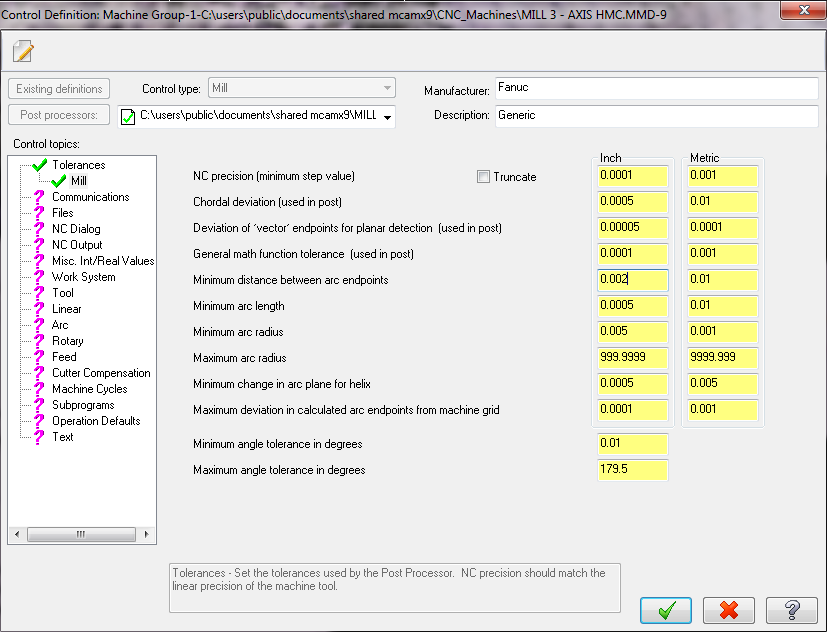
What is the min arc radius set to?
.0001 set by MASTERCAM DEFAULT ARRRRRR. I'm almost 100% sure this is the issue. I changed it to .005 per your recommendation. I'll know for sure in a few hours.
Go in mach def, break arcs or do not allow 360deg arc.
This is set unchecked as defualt for the HMC 3 axis post... Also set to quads as defualt...
-
i will do testing on monday... first ill take smoothing to segments off and change the min. arc. rad
if this doesn't gouge i will change back the min arc to the default to see if the gouge 360 thing will show up again....on a piece of regular 6061 alum.
I can't be scraping anymore brazed assemblies.
.gif)
THANKS GUYS i will report back
Allow 360 arcs was never checked and i have it breaking arcs at quads..
-
I'm def. leaning towards min. arc being the issue... cause it bit me on a setup piece and since than i have been back plotting all repost of this program to this control
-
Hey gentlemen,
I had an issue today with GENERIC 3AXIS HMC POST.
I was using Horizontal Toolpath with filtering off and tolerance set to .001.
The path ran on a Fanuc 18i controller. Two arcs did a full 360 gouging the part.
So i set to smoothing fixed segment and the problem wwent away. Is this a common problem?
looking for the low down here.
Any advice?
-
IMO you don't. I make a program one time and never repost it unless I need to edit the cutting data or create/remove tool paths. I avoid running partial tombstones as there as the benefit does not out weigh the faults for my situation. My production multi parts programs are usually sub 30min per part, the longest is 1hr/part and the shortest is 5min/part (not per tombstone), so by removing 1-2 parts for a partial tombstone there isn't much in the way of time savings, and when you factor in having operators d1ck around adjusting fixturing to run partial tombstones, change macro parameters etc the benefit ceases to exist.
well i could see that but sometimes we want to run one part to make adjustments and other situations... i only post one part never have to renumber tool or touch offsets so i like this system
-
Still doesn't seem flexible enough. Why would you want to repost every freaking time. Just post one program for one part and have macros!?!
-
this is pretty good logic for only having to post a single part program on a horz
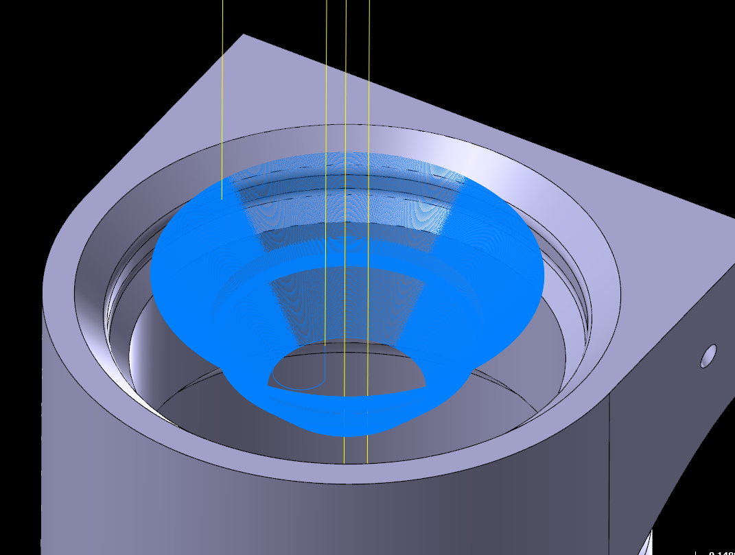
O-ring Boss Port Question
in Machining, Tools, Cutting & Probing
Posted
Can't win them all.