mmoya
-
Posts
33 -
Joined
-
Last visited
Content Type
Profiles
Forums
Downloads
Store
eMastercam Wiki
Blogs
Gallery
Events
Everything posted by mmoya
-
Good find. An almost identical build from ecollegepc.com (only difference is RAM) is$2559 built w/ parts & labor warranty, although I don't know anything about their customer service..
-
Thanks for the tips. The SSD would just be for the OS, I could go way smaller than that but I was just trying to compare it to the BOXX. 27 inches! LOL I might have to pick up some CRT's from goodwill to stay in budget
-
Excellent point. That's why I want something that just WORKS If your shop has $500k worth of equipment, a $5k BOXX is 1% of that.
-
What you think about this, with the exception of the video card: Intel Professional Series Configurator : Intel Core i7 7700K 4.2Ghz 8MB Cache Quad-Core Noctura NH-D15 SSO2 D-Type Premium CPU Cooler, ASUS Prime Z270-A (Intel Z270, HDMI, 3xPCI-E, 7xSATA, 4xDDR4) 32GB (8GBx4) PC4 17000 DDR4 2133Mhz Memory Lifetime Warranty (Major Brand) 500GB SAMSUNG 960 EVO Series MZ-V6E500BW PCIe M.2 1TB Western Digital Black 7200RPM 64MB Cache SATA3 6Gbps 8GB GeForce GTX 1080 GDDR5X PCI-E DVI/HDMI/DP (Major Brand) Microsoft Windows 10 Professional 64bit (Includes DVD + COA) 750watt Corsair RM750x Modular 80 PLUS GOLD CERTIFIED | $2476 Built
-
BOXX aren't cheap, but for 4 grand, I can configure a fairly powerful machine with liquid cooling all ready to go out of the box and like you said, with a warranty. I haven't seen any massive complex files yet, they're typically fairly small and straightforward parts. I haven't seen any mcam files more than maybe 75mb, but that doesn't mean I never will.... Right now I'm programming on what is basically a word processing machine with a Quadro K2200. It's infuriating. From what you're saying I would guess we probably wouldn't need a $2,000 Xeon. Is there some kind of threshold though? Like don't buy anything lower than "i7 XXXX"? RAM is easy, so is PSU. But for the graphics card, we need to be able to open and navigate large Solidworks assemblies. Again, is there some threshold for that? All the engineers machines run Quadro cards. As far as building vs buying, I personally don't care, but another question then would be what mobo to buy? I'm sure that has a whole slew of specs to figure out in order to support the CPU, graphics card, etc as well..
-
I'm putting together a proposal to buy two new workstations at work. I previously pitched a budget of $5000 per machine which gives plenty of room for selecting the best hardware. Our IT guy is on call and is only around a couple days a month, so I'm looking at pre-built options rather than a custom build. I found a place that modifies and optimizes Dell machines specifically for Mastercam, and this is their most powerful machine: http://mysolidbox.com/mastercam/product/carbide-desktop-level-2 Looking at the specs it seems overpriced for what it is. I've been browsing around on boxx.com and their sales team suggested the APEXX 2 2403 which comes out to about the same price with similar hardware, with the only main difference being the processor.. I know that higher clock speeds and more cores are better, but I don't have any idea beyond that. So my question is this: What kind of processor should I be looking at? How many cores? What clock speed? Cache size? Also what graphics card would be a good choice? Are there other places I should look at besides BOXX? We use every kind of toolpath there is (we do a lot of one-off work) and will be getting into the 5-axis arena soon, these machines will need to be able to pull their own weight for the next 5 years as well. Sorry if I sound like a noob, I haven't bought a computer in like 5 years
-
Using custom tool geometry in simulation/verify/backplot?
mmoya replied to mmoya's topic in Industrial Forum
Well this was not to the instructions shown on the PDF. I wrote that before seeing the post with the PDF, which I mentioned earlier.. The very first method I tried, was from the help section in Mastercam: Which failed. So then began the experimenting.. I just played with it some more and got the dxf to work but only when the entire profile was in quadrant #1, which is not what the help section stated. -
Using custom tool geometry in simulation/verify/backplot?
mmoya replied to mmoya's topic in Industrial Forum
Didn't see this till my earlier reply. For some reason, using the DXF method still will not work. I've tried every which way to no avail, but using the MCX (vertical) method worked! Thank you AlbertZini! Edit: What was throwing me off the most was that it imported and displayed correctly in the tool manager, but didn't work in any sim/backplot.. I didn't even think to use a MCX file rather than DXF -
Using custom tool geometry in simulation/verify/backplot?
mmoya replied to mmoya's topic in Industrial Forum
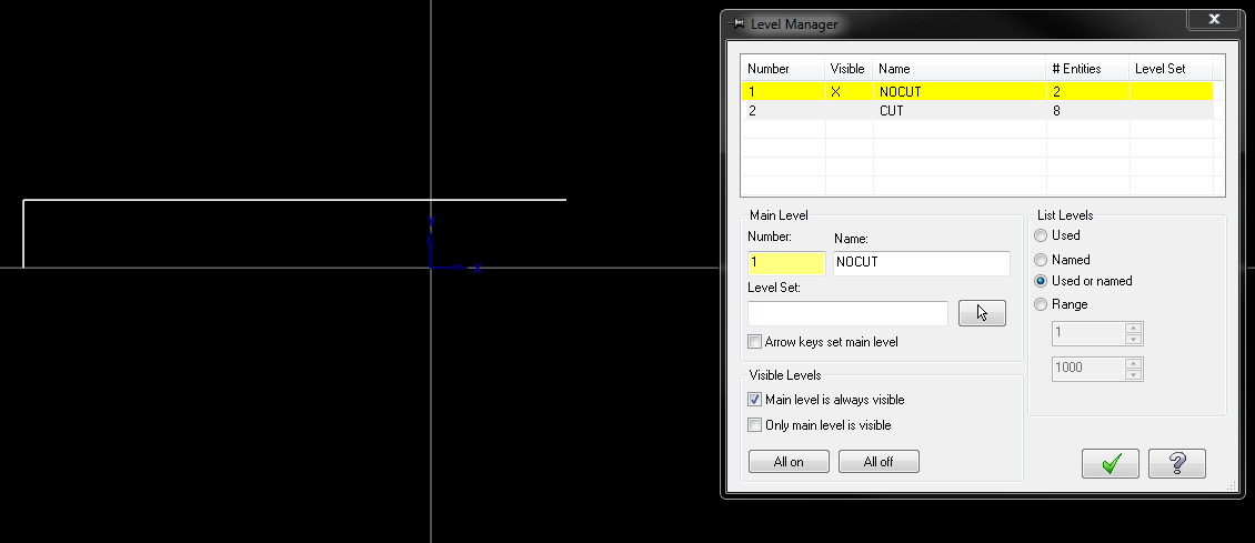
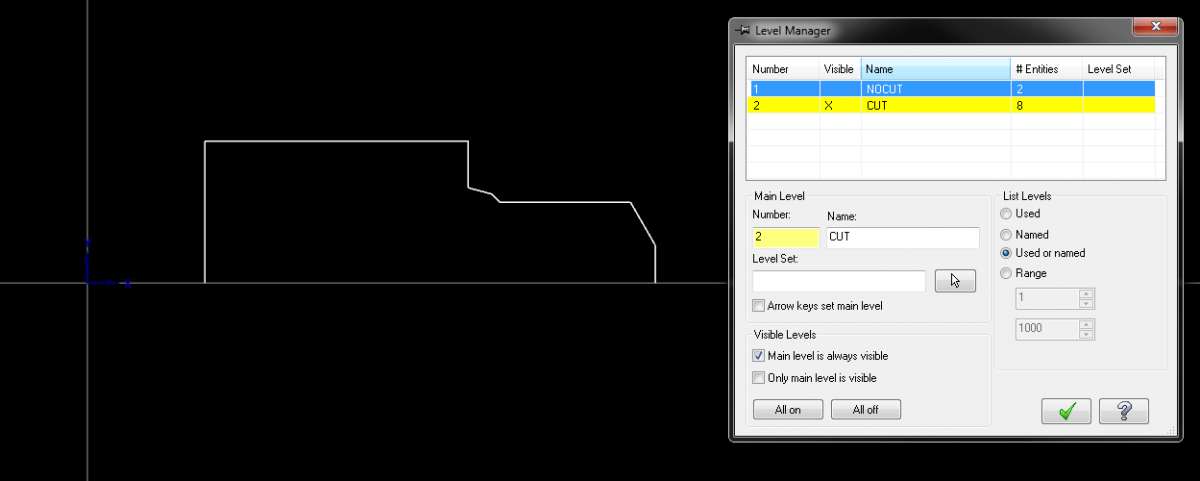
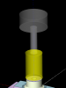
I have everything oriented correctly, on the correct levels, and with the correct geometry, afaik. See pics.

-
Using custom tool geometry in simulation/verify/backplot?
mmoya replied to mmoya's topic in Industrial Forum
It is on XY. -
Using custom tool geometry in simulation/verify/backplot?
mmoya replied to mmoya's topic in Industrial Forum
Just tried it and still gives me the error -
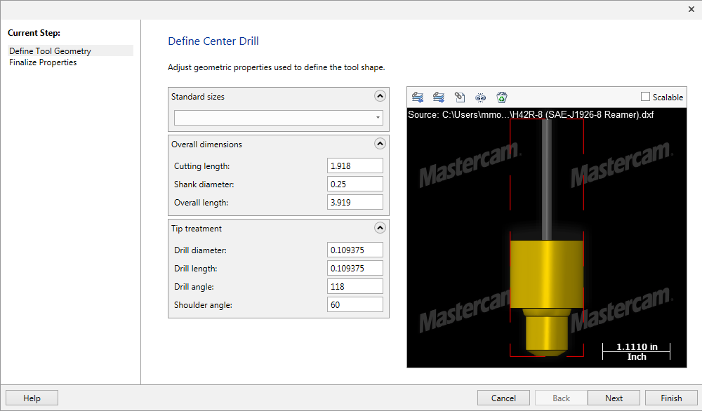
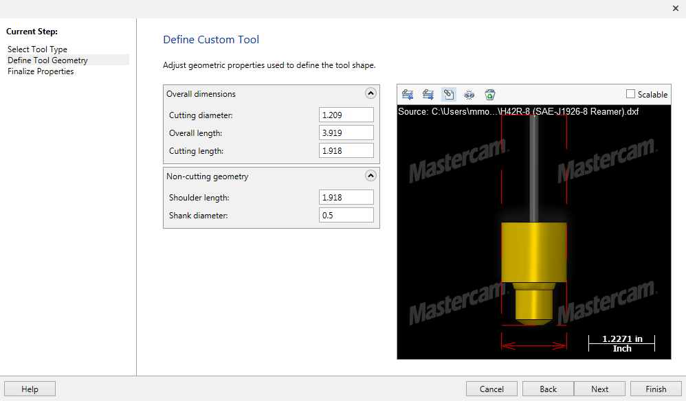
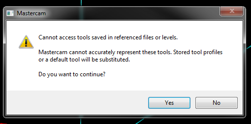
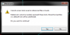
I created a custom reamer in Mastercam using a DXF file of the tool profile, but when I go to sim or verify I get an error saying "Cannot access tools saved in references files or levels. Mastercam cannot accurately represent these tools. Stored tool profiles or a default tool will be substituted. Do you wnat to continue?" If I choose yes, it just shows a cylinder that's the same size of the biggest portion of the tool. I tried picking "Custom" tool type and "Center Drill" since it's the closest in shape. It's a boss port reamer so I need to be able to sim it to make sure it's doing what I want it to do.. I attached a couple screenshots for reference. Any help is appreciated! p.s. I'm on X9

-
I think I'll call HAAS again to see what they say. I know they give them out for free as long as I'm a CAM user, but when they gave me the machine model for our ST-30 last December they said that the VF-4 model "wasn't released yet" and to check back later. I've played around with that, but it seems like the zero in the machine sim is at some obscure location, so I end up punching in different numbers through trial & error trying to get it located correctly in the sim. When I run it in 3-axis mode the WCS/TP zero is embedded somewhere inside the machine table, and in 4-axis the zero is inside the trunnion, and way off center, as you can see in the screenshot. What about the Post Settings and Machine Definition tabs? There's gotta be some configuration setting somewhere besides the workpiece translation.
-
Welp hopefully I can get my hands on some machine models so i can at least do some manual collision checking. HOWEVER- it still doesn't solve the issue in my first post... Has anyone been able to fix it? For the amount of money that we pay for Mastercam you'd think they would give us a decently working simulator...................
-
Yeah I suppose you're right with the storage thing... But GrabCAD doesn't have our machines I tried before and was told that machine models are only available through a reseller. Called my reseller and they said HAAS hasn't released them yet...
-
Hmm. Seems like a good workaround, but wouldn't that make the MCX files really heavy with all those solids in there? That also wouldn't show me any kind of "as-cut" model either, which is something I like to see. Ideally, I'd get Vericut, but my company doesn't want to spend that kind of money right now. I have models for our vices and table, but not for the Trunnion, and definitely not a machine model. I call my reseller every now and then for machine models but HAAS has yet to release a VF-4 model.
-
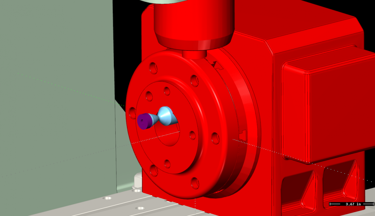
I've been programming in Mastercam for about 2 years now, but I've never liked the simulation feature that comes with mastercam. I've always had so many issues with it I try not to even use it. There have been instances where the sim is 200% fine only to have the machine nearly crash, or on the other hand the sim is just completely wild with the spindle halfway through my workpiece but the g-code posts correctly. So I just baby the machine for the first run and end up having to go back and fourth from the machine to my workstation while I try to iron out my program... I just finished a 4th axis part and went to sim it, and when I view it with the machine housing it looks like this: What gives?? I've tried to edit the machine settings in Mastercam and in the simulation windows but haven't had any luck. Am I the only one? I'd really like to get this thing to work correctly...

-
I'm using the included "Generic HAAS 4X Mill." If I set my min/max to those values, what will happen if I post a axis-sub toolpath like the one that commands 4k degrees? I've been reluctant to switch to MPMASTER because I don't know how the machine will behave. I'm having a hard time understanding the post and how to modify it without fcking anything up. Here's a snip of my program for reference, you can see where I had to manually add the G91 G28 A0 & G90. N66460 G94 G1 Z1.0067 F5. N66470 G42 D2 X-.4429 A-298.034 N66480 X-.4061 A-297.959 N66490 X-.3696 A-297.606 N66500 X-.3337 A-296.981 N66510 X-.2988 A-296.091 N66520 X-.2652 A-294.943 N66530 X-.2332 A-293.549 N66540 X-.2032 A-291.922 N66550 X-.1754 A-290.079 N66560 X-.1501 A-288.036 N66570 X-.1275 A-285.814 N66580 X-.108 A-283.433 N66590 X-.0915 A-280.917 N66600 X-.0784 A-278.29 N66610 X-.0687 A-275.578 N66620 X-.0625 A-272.806 N66630 X-.06 A-270. N66640 G93 X1.14 A4050. F.1 N66650 G40 A4410. F.8 N66660 G0 Z1.2567 N66670 X-.8178 G91 G28 A0. N66680 G90 Z1.2067 N66690 G94 G1 Z.76 F5. N66700 G42 D2 X-.4429 A-298.034 I've done this already, hence why I explained that manually typing in G91 G28 A0 works in my op.
-
bump
-
I searched that variable and it comes up three times. Once in the Rotary Axis Settings section: frc_cinit : yes$ Once in the Start of File and Toolchange Setup section, about 40 lines down from "pretract #End of tool path, toolchange" #cc_pos is reset in the toolchange here cc_pos$ = zero gcode$ = zero if use_rot_lock & rot_on_x, [ if (index = one & (prv_indx_out <> fmtrnd(indx_out)) | (prv_cabs <> fmtrnd(cabs))) | nextop$ = 1003 | frc_cinit, prot_unlock ] And once more in the same section but further down, protretinc #Reset the C axis revolution counter if frc_cinit & rot_on_x, [ rev = zero sav_rev = zero cabs = zero csav = zero indx_out = zero if index, e$, pindxcalc, pindex else, *cabs prvcabs = zero !csav, !cabs ] rot_on_x is turned on, and use_rot_lock is off. I'm not sure what i'm supposed to change.. I'd rather not have to force a toolchange because then it puts an M01 after each pass. I put M01's in the program sometimes in case i need to tell the operator to do something, and if op-stop is on, then it retracts and stops all the time which defeats the purpose of it...
-
We have a new VF-4 with the HRT-210 rotary, we're using the rotary for the first time on this machine and so I wrote some test programs to make sure everything moved correctly. My tester was a spiral shaped contour along X and I used axis substitution for Y so the spindle basically just sits at Z and moves along X while spinning the rotary, now after 10 or so revolutions the rotary winds up to about 4000 degrees, and when the spindle retracts for a second pass & commands A0, the rotary has to unwind all the way back to 0 which is suuuuuper slow. G91 G28 A0 fixes the problem but I have to punch it in manually between passes. I tried browsing through the post to see if I could find something for it to no avail. I went into the MD on mcam and selected "Shortest direction, absolute angle" instead of "Signed continuous" and that didn't change anything either. Could someone help me out?
-
Milling: Cutter compensation & lead-in/out arc
mmoya replied to SlaveCam's topic in Industrial Forum
So update... The problem has been corrected; BUT, I still don't know what caused it. I tried everything that was suggested and nothing seemed to fix it. I moved the starting point from the left edge of the contour to the right edge, just to see what would happen, and it magically worked! Moved it back to the left and had the same problem. I guess MCAM just didn't like it... Part is done though so I'm happy! I'll take most of your guys' advice and stick to Control comp and see how things work out. Our last mill was pretty much a "base line" 2007 TM2, so we're still getting used to the bells and whistles of our new VF4! -
Milling: Cutter compensation & lead-in/out arc
mmoya replied to SlaveCam's topic in Industrial Forum
Ah, a new day. Let's see if i can convince mcam to play nice today. Gouge check is selected, deselecting has no effect either.... We're using control comp because the WIPS system on our VF4 has automatic tool probing, but it registers the tool diam in the actual diameter column rather than adding a wear offset. If there's a way to change this, I'd much rather run wear compensation. -
Milling: Cutter compensation & lead-in/out arc
mmoya replied to SlaveCam's topic in Industrial Forum
I too am having this problem. Got a alarm 357 cutter comp interference because the arc was 50%. Changed lead in/out arcs to 100% and didn't get the error. BUT- when we ran the program, the machine ended up taking a huge bite out of the side of the part that should have been a .003" finish cut... My mistake is I only backplotted instead of simulating, but the issue is still not resolved... This is the first time we've ran control compensation. It looks as if the cutter is following the toolpath at the center of the tool during lead in/out, and at the end of the lead/beginning of toolpath, it switched to cutting edge...
-
Does anyone have an english translation of the Excel template? I've been using the html version but its pretty limited on formatting, and looking at the excel template, it looks way easier to customize and actually add content such as form numbers etc.. My only problem is that all the instructions in the VB script are German and I dont really know VB well enough to know what I'm looking at, but if the instruction comments were in english then at least I'd be able to make sense of it.