


mmoya
-
Posts
33 -
Joined
-
Last visited
Content Type
Profiles
Forums
Downloads
Store
eMastercam Wiki
Blogs
Gallery
Events
Posts posted by mmoya
-
-
With tool inspection the post has to be set up to handle per machine. What you are asking for could be handled many different ways, from a mi trigger to cantext with the toolpath editor. The best way would be using the tool inspection and taking the time to change the post to support it. Dealers are always your 1st line of support, but if you want to hire an outside company to help you tackle this there are companies like ours that will helps if and only if the dealer options have been explored.
I understand there is a setting in the post for tool inspection support, but would that post setting dictate when or how often that happens even when there no option for it in the toolpath manager?
I don't even want a "tool inspection," all we need is a break in the program every few operations, not every pass.
-
Okay so its a 2D Contour toolpath witha 3D contour, I want a toolchange before it starts because the toolpath before it uses the same tool.
Our operator asks for this so if anything happens in the middle of a program, he can skip over the hours of machining that's already been done in order to resume at the nearest operation.
Problem is, when I run the program, the damn machine stops, retracts the spindle, sends rotary to 0, and then starts again, after EVERY pass! and theres 8 passes!

Looked at the Gcode and obviously it has inserted a "toolchange" after every pass. Clearance "use only at end of op" doesn't make a difference. The toolpath window doesn't even display the tool inspection options. What can I do to change this? Post setting? Why on earth would someone want this to happen every pass?
I could do it manually, but I really don't want to. I need a bunch of forced toolchanges because the program runs the same tool for like 4 hours and 16 operations.
Here's what outputs at each pass:
M5
G91 G28 Z0. M9
A0.
M01
-
When using the Generic posts that are supplied with Mcam the minus one in the work offset value tells the post to pickup the next available work offset.
Try changing your work offsets for each operation (or rotation) from -1 to 0. This should get the output you are looking for. HTH
Okay that's what I had wrong, I knew that I needed to have all the offsets the same value but I didn't know that the -1 did that!
I am using the generic HAAS 4x post, I tried to modify/customize it to suit our needs as much as I could with the knowledge I have on posts (which is pretty limited.)
I want to stay away from locking in just one offset because in the future I'd like to take advantage of using multiple offsets.
Go into your WCS Plane manager.....all the planes with a blue check mark by them...set work offsets to 0.
Edit the planes in all ops...set WCS to TOP/x/x where X = custom plane. The top plane is the only one that will say top/top/top. All other planes will be top/x/x.
any legacy toolpaths should default to rotary axis positioning in the axis control...don't change that...
All HST's should default to no rotation....don't change that...
The post will take care of the rest..
You say that the HST's should not have rotary axis positioning, but all others should? Why is that?
When I create my first toolpath, I select rotary positioning, and then all subsequent toolpaths follow that selection. I haven't see any issues doing it that way, but then again, I might be completely wrong..
I'd like to also mention some more detail about my earlier question, might help someone else out one day.. We found the best way to find A0 was using a digital inclinometer set on the dovetail fixture (it has flat faces on two sides). Match it to the table and done, takes 10 seconds. Then rotate 90* and use an edge finder on the fixture, minus distance to centerline, to find Y.
-
Okay so using your guys' advice, I left Z0 and Y0 at the center of rotation, and X0 was set on the left face of the stock. Got dimensions for our fixture and we were able to get the zeros correct. Great!
Now my problem is that when the rotary should index to the next position, my G-code outputs G55, and the next rotation it outputs G56, etc..
Here's an example,
N100 G20
N110 G0 G17 G40 G49 G80 G90
N120 T2 M6
N130 G0 G90 G54 X2.1703 Y0. A0. S1200 M3
N140 G43 H2 Z3.
N150 M8
N160 Z1.6
N170 G1 Z1.475 F2.
N180 X1.0851 F4.
N190 Z1.575 F6.4
N200 G0 Z3.
N210 G55 X2.1703 Y0. Z3. A-90.
N220 Z1.6
N230 G1 Z1.475 F2.
N240 X1.0851 F4.
N250 Z1.575 F6.4
N260 G0 Z3.
N270 G56 X2.1703 Y0. Z3. A-180.
It's been a long day, I don't know what I'm missing...
-
So we just installed an HRT-210 rotary on our HAAS mill. Our lead machinist has set it up with a Raptor dovetail fixture mounted on an adapter for the rotary table.
My question is, what is the easiest way to set Y-zero on the machine in relation to MCAM (x8)?
In MCAM I have the program with Z and Y at the center of the part, with multiple T planes at their respective degreee, all centered at the same point. Realistically, I think that's the best way to do it (if not the only way) and simply use an edge finder on a flat face of the Raptor fixture, and subtract the distance to the center of it for Y0. What do you guys think?
Another idea was, when I set toolplanes on MCAM, and set rotary axis positioning in axis control to rotate about X, is it rotating about T/C plane X? or WCS X?
If I were to make a T/C plane with Y0 off at some random point (which would dictate where X axis is located), will the program try to rotate about the offset X-axis? or would it continue to rotate about the WCS axis?
Hope this makes sense...
-
nah this has been going on for so long I just started using a workaround to get it functional again saving a stock model or stl before each and every rotation and only check the toolpaths after that stock model.
That sounds horrible. What do you do if you have 6 or 7 rotary positions with a stock file for each and have to go back to change something in the beginning of the program? re-sim and save all those stock models again? I'd rather put my head through the monitor.
Looks like you lads are suffering from your control def not being set to match your machine. I'd take a look at this thread and make sure that you have it set up right:
As for verification rotating the part vs. the tool, change your focus instead of focusing on the workpiece, focus on the tool. That will keep the tool vertical and rotate the workpiece instead:
Holy guacamole, so the post in that thread mentions the rapid movement setting in the CD, I set it to "All axes arrive at destination simultaneously" and it fixed it! It still doesn't show the rotary movement, it sort-of just cuts to the next angle, but 99% of the time i have focus set to "part" since we don't actually have a machine model that represents our HAAS - at all. Matter o'fact the model for the 4x rotary in simulation is on the opposite side of the table... never was able to fix that....
-
I was hoping someone could help with this problem...
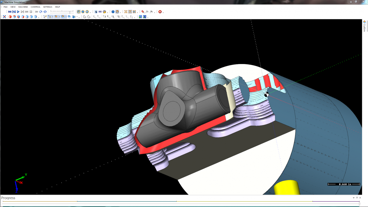
I am trying to simulate toolpaths on X8 for 4-axis (rotary axis positioning.) However, when I run the sim, at the point which the part should rotate 180 degrees, mastercams simulator bottoms out the cutter/holder, which "collides" with the stock and workpiece before flipping over to machine the other side.
Its not that the toolpath is causing this, but something in MCAMs simulator instead of retracting the tool 2" it just plunges.
It's not just this part, either. Every time I've tried this, the same thing happens... I have my MD set up, NC output is fine, its JUST in simulation or verification.
Anyone had this problem? Seems to me like either a setting or maybe (hopefully not) just how MCAM interperets the retract and rotation for simulation.
I attached a screenshot of the end result of the sim..
Force tool change retracts and stops the spindle after every pass!
in Industrial Forum
Posted
Exactly. One operation might have 5 to 10 passes, and if there's a forced tool change on 5 op's, thats a ton of wasted time..
Sorry if my post was difficult to understand. My hands type faster than I can think sometimes.
Any advice on where in the post I could investigate? Things to look for?
I'm using the generic HAAS 4x post that I lightly modified. Though I don't remember changing anything that could've caused this issue....