tiredtoolmaker
-
Posts
124 -
Joined
-
Last visited
-
Days Won
3
Content Type
Profiles
Forums
Downloads
Store
eMastercam Wiki
Blogs
Gallery
Events
Everything posted by tiredtoolmaker
-
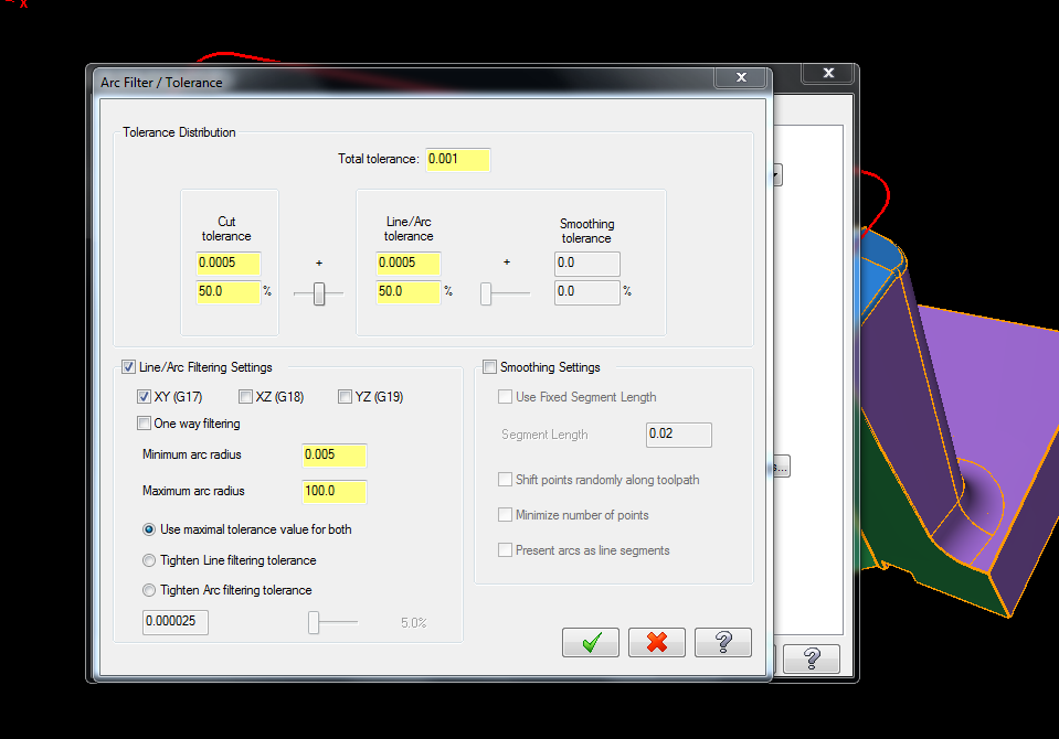
Re: MX7 See attachment The instructor of the Mastercam classes I've attended told us to always check the line/arc filter settings box and move the slider to 50% especially on older machines that have slower processors. I have always followed his advice and would like to set this setting as a default, if possible. I have a feeling I might get hammered for wanting to use this setting for every job regardless of the jobs tolerance specs. Please advise.
-
How can I lock these fields in Mastercam?
tiredtoolmaker replied to Rocky16's topic in Industrial Forum
Thanks for all the info guys. I did attend several classes and was bombarded with so much info it was impossible to digest. I scribbled notes which made little since when I returned to work. I depend on you guys for guidance since I have no one at work that knows anything about Mastercam. -
How can I lock these fields in Mastercam?
tiredtoolmaker replied to Rocky16's topic in Industrial Forum
Ok I wrong but my 1/2" ball that's tool #5 today might be tool #7 tomorrow. I can't always use the same tool in the same slot. So once again, I'm changing tool #'s. Am I a total idiot for thinking this way? -
How can I lock these fields in Mastercam?
tiredtoolmaker replied to Rocky16's topic in Industrial Forum
Pardon me but I am simple minded and can see where Rocky's idea is useful. I have one machine to program, a Haas with a 20 tool carousel. With all the hundreds of tool #'s in the libraries, I always have to change the tool and length offset #'s. I always use the same # for each value. Am I wrong or don't have my stuff set up right? Again, I'm not programming a shop full of machines...just one. -
How can I lock these fields in Mastercam?
tiredtoolmaker replied to Rocky16's topic in Industrial Forum
That's great...so how did you accomplish this? -
I was doing a repair job and needed to do some Z axis editing at various points while at the machine.
-
Thanks. I played with the parameters and was able to generate all lines to points only.
-
Thanks...that did it.
-
Re: X7 I had a vertical toolbar on the right side of screen that listed the last functions used. I have lost it and don't see anything in the list to turn it back on. Please advise.
-
Maybe I wasn't clear in my request. I found under parameters/arc filter-tolerance/smoothing settings/present arcs as line segments. I selected this and still have (2) lines containing I's and J's. I don't understand why it didn't convert these two lines out of a 3000 line program.
-
I want to post to a Haas VF6 using point to point instead of circular interpolation. I'm looking at the post in Control Definition Mgr but don't see anything. Please let me know how to do this.
-
On a different note, years ago, we tapped 10-32 holes in hundreds of thousands of titanium parts. Our now deceased NDT engineer came up with a mild acid mixture (customer approved) that dissolved the taps but had no effect on the titanium. We had a plastic vat that we lowered the parts in and several days later the taps were loose enough to remove with a pair of tweezers. This was a very inexpensive process.
-
Is it possibly in your AutoCursor settings?
-
I believe it is because there is a chamfer when you remove the fillet in the model. At some point, the designer added the fillet to the existing model.
-
I did what Teh Bear suggested. Now it states I have dirty, invalid or suppressed operations. I regenerated solids and still get this message.
-
Re: X7/Solids/Modify Solid Feature As you notice in the model, this function allowed me to fill all features except for one counterbore. Is it possible to fill this hole using this method? MOD.MCX-7
-
Dynamic Xform Multiple and Xform Translate
tiredtoolmaker replied to mario's topic in Industrial Forum
Huh? -
Thanks...I completely understand now that the centerline of ball becomes datum instead of tip.
-
If you run verify in this file it shows the undercut around the profile of the bottom of the pocket. I used center of tool instead of tip in cut parameters to accomplish this. The pocket is .500 deep so the Z depth in the post should be -.625 since I'm using a 1/4" ball mill. I'm getting a Z depth of -.500 in any machine post I select and not getting the undercut I desire. I tried using control instead of computer in cut parameters/compensation type but this creates even more of a mess. I know I can use the tip of the tool and change stock to leave on floor or simply change my depth in linking parameters but that doesn't tell me why verify shows the undercut but the post does not. What I'm I doing wrong here? Thanks for any help. DITCH.MCX-7
-
Drilling random holes down hill
tiredtoolmaker replied to tiredtoolmaker's topic in Industrial Forum
I don't think you could beat the first way you said. It took me maybe 30 seconds to accomplish. -
Drilling random holes down hill
tiredtoolmaker replied to tiredtoolmaker's topic in Industrial Forum
Thanks Teh Bear...I knew it was going to be simple. -
I'm not an idiot at Mastercam but not an expert either. This is the first time I have ran into this issue. I attached the model as a solid with no curves, etc. I'm looking for the best way to drill these holes without having wasted time drilling from a single reference plane. It's too much trouble selecting each hole and adjusting the linking parameters. Is FBM or stock model machining an option as I have no experience using these? I feel this is simple but I'm drawing a blank. Thanks for any suggestions. BLOCK.MCX-7
-
When opening the backplot window, is there a setting to make it open expanded to show the info section?
-
End or side, I would always use a junk end mill for a job like this. Even a POS will usually still cut.