


Resunonac
-
Posts
8 -
Joined
-
Last visited
Recent Profile Visitors
220 profile views


Resunonac's Achievements
")


-
Hi Jespertech I think, maybe, i found the setting which created the problem. In the 3d tool creator/ compensation tab, I switched the plunge/cut direction and then i worked perfect - like the other 2d tool. Maybe I am misunderstanding plunge/cut directions, but now I know where to look, if the problem comes back again. Thanks for trying to help me out here
-
I am on a HLE version. Hope it works anyway emastercam.TOOLDB groove_1mm.emcam
-
Hi Jespertech Everything works fine with a normal 2d tool. the problem is only with the 3d tool. I tried to play with start/end of contour. But without any luck
-
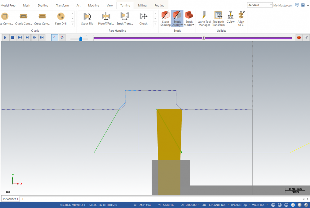
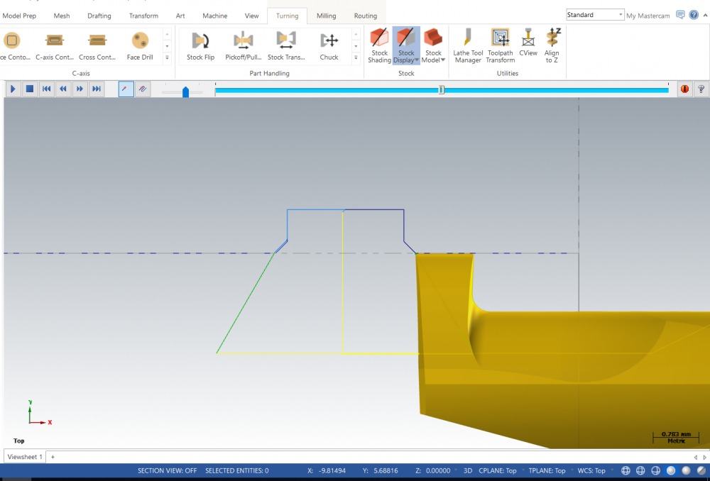
Hi I am having some problems with a 3d tool for internal grooving. It is made from stp files supplied by the manufactor. When I create a lathe groove finish toolpath with the new 3D tool, the tool cuts differently than using a regular 2d created tool. The first image shows the 2d tool, on the second pass lead in. It begins cutting only with the right corner. The second image is the 3d tool. On the second pass it moves to a full width contact, before moving to the chain geometry selected for the operation. The geometry used for the two finish groove operations are only the groove and the chamfers. And the parameters are identical. It must be a mistake i have made when creating the 3d tool, but i havent been able to figure it out yet. Hope you can help.
-
It was a company decision. Not sure about the details..
-
I am using finish path. But I am thinking about how to do this on an shaft with different tolerances. I can't add a value which suits all diameters. If I have three different diameters on my part, with each of their own tolerances, I can't adjust it via Stock to leave.
-
Hi I am switching from Edgecam to Mastercam, and I have a few small problems. If I am working on a solid, made on 0, and want to add a h7 tolerance to a cylinder piece. How is that possible in Mastercam Lathe 2019? Do I need to add another line at the correct diameter, or is it possible to give an offset value to a line segment? Thanks
-
Hi Can someone help and tell me how I can keep $PATH in a CIMCOEDIT macro. I want the output to be this: ;$PATH=/_N_WKS_DIR/_N_1041_WPD unfortunately there are already a variable in cimcoedit with the same name $PATH. So when I run the macro I get this: ;=/_N_WKS_DIR/_N_1044_WPD Regards


