Kampfzentrum
-
Posts
125 -
Joined
-
Last visited
Content Type
Profiles
Forums
Downloads
Store
eMastercam Wiki
Blogs
Gallery
Events
Everything posted by Kampfzentrum
-
OK, this string of code, where are you accessing this?
-
You know, so I have to ask, what are all these various axes for anyway. I swear, I know it must serve some flexibility, but it all seems repetitive and confusing. All I'd like is a part orientated on the screen running parallel to the WCS top axis (through Z). I tried the generic VTL definition, same thing I don't see a difference.
-
Thanks. Yeah... Option 1 seems a bit more up my alley, I've never modified the post - where does one even learn to do that?
-
So one of my operators comes complaining to me, he's upset because Mastercam posts so many redundant paths in the same axis. For instance, if travelling in X Mastercam will program a lead in (in the case that the lead in is on line with the path, no arc/perpendicular lead in), the tool path, then lead out. What this does is leaves multiple blocks all in the same direction when really Mastercam could just be intuitive and delete the additional unnecessary blocks. In case I'm not being clear: G01 X5.000 X10.000 X15.000 G00 Z4.000 This would also help out with other machines where I have to enable the "look ahead" feature or they stutter on each one of those positions. The same goes for arcs, any advice?
-
Set this up in the Machine Parameters? Any specific default Cplane I should work out of?
-
So, I've managed to avoid HTL and VTL for years now, but it's time to face the music. Programming toolpaths I've been successful with, but what is stumping me is part view/orientation. I've read the forum for past posts and have not found much to go on. Right now, all I am asking is for one thing: to be able to view the part in its correct orientation. For instance, if I click on TOP view, I want to view the part from the top with gnomen showing X pointing right, Y pointing up, etc. If I go to front view, I want to see X pointing right, Z pointing up. This is familiar to me and makes sense. If I generate stock, I want it to be constructed parallel to the Z axis, etc. Once I have a proper perspective, I can create toolpaths, etc. But right now I cannot even get my bearing when looking at the part. Sooo... In the Machine Definition, what is the most convenient Default Cplane/Orientation/Update WCS Using? Anything else that can be added to these changes to make my life easier? ADDITION: I guess I should add that the tool is and carousel is located on the right side from the operator, but from what I hear you need to set it up as a left-hand machine? I'm really confused about all this - then I hear about 2019 and the new update, etc. I'm just wanting to view this in a way that is practical to me. ALSO, the post processor I have is old as dust, it's an MPLMaster and I've heard that earlier versions don't have proper VTL perspectives - surely this must have been edited. HELP!
-
Awesome, thanks guys.
-
I apologize if this is a common question or found widely on the forum, I could not find any details. I know how to convert an SAE document to a metric one using the Settings > Configuration > Current, etc... But here's my issue... I have a huge drawing done in metric. Instead of 25.4ing every dimension, I'd like to draw it in metric and then POOF! convert it to SAE. But when I do so using the above steps, the drawing scrambles and doesn't resemble anything like what I should get. Is there another way to transfer the drawing from SAE to metric that I'm missing?
-
COMPLETELY DUMBFOUNDED: Simple Bevel in 2D Contour
Kampfzentrum replied to Kampfzentrum's topic in Industrial Forum
Well isn't that just a dandy... Thanks Colin (and everyone who responded), I moved the geometry for the toolpath down to the part and VIOLA! It generated. I really didn't think that 2D toolpaths even looked at the part, but somehow it is related. I need to get an orthodox education in this stuff. I just want to say I really appreciate the help I've gotten on here. It's saved my butt a few times - like now. -
COMPLETELY DUMBFOUNDED: Simple Bevel in 2D Contour
Kampfzentrum replied to Kampfzentrum's topic in Industrial Forum
Where is that parameter? I don't see where that would be changed, it's just a 2D Contour. -
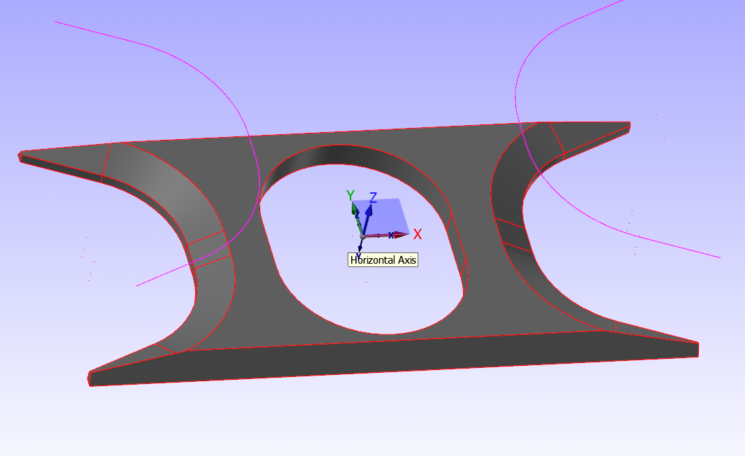
So I got this simple part, just need to machine a bevel on it. I go into Contour, select the geometry path (seen in image); in Depth Cuts choose a .030" stepdown, check Tapered Walls (w/ angle of 63.4), Step Down, etc. Linking Parameters set, etc. Upon regen it tells me Cutter Compensation Not Successful. After so much I give up. I WILL generate a tool path if the angle is less than 15 degrees, but anything over that it will not do anything. What am I missing?

-
Are they already discussing 2019? Why don't they just update 2018, sheesh... But seriously? Cannot do this?
-
OK, let me ask another question. In the case of a standard turn/face tool on a VTL. Most people would run a turning tool on the left side of the part using M04. However, because of the type of parts and the rigid system put in place, these guy manually program parts where the tool crosses over the centerline of the part onto the other side to face and bore using M03. I am not seeing this ability to change this on the fly, where is this parameter?
-
Awesome... Thanks so much!
-
Call me crazy... But why does it seem that during any backplot simulation the tool that I created (that you edited) takes off more stock than the feature itself? Tool looks to be plunging into areas it shouldn't be.
-
Man, thanks so much for your help and time. I have much to digest here, thanks.
-
I'm not even doing 3D, I'm just doing a wireframe and it seems like madness. I honestly can only blame myself as I haven't had a formal education in any of this. I'm really just trying to wing it.
-
I still really am lost as to how you got the tool orientated correctly. I deleted the operation, deleted the tool completely, edited the tool and set the cutting edges for X0 and Z0, re-created the operation, imported the new tool, chose a "face" groove, and yet the tool is still cocked. I cannot see what you changed to get that dang thing orientated the right way.
-
Wow, I'm really far away from getting this. I'll be diving into this file. Much thanks.
-
What setup screen would you like to see? I am not sure what screen you are requesting. I personally drawn the tool just as you described. I am not sure why it is inverting it like it is. Zip2Go posted. 2039916A.ZIP
-
Well, I'm glad to hear I'm not the only one going nuts over this.
-
I actually tried that already. I set it to this value after it was doing that.
-
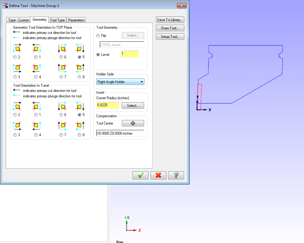
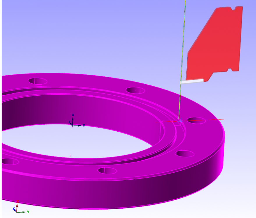
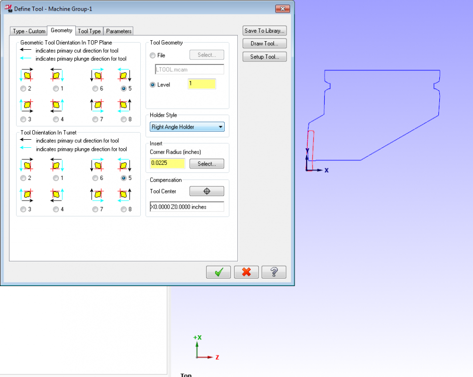
Morning gents, got a perplexing issue here. I'm new to a company that has handed me the responsibility of creating a full graphical tool list for their VTL. I've drawn the tool up and saved it to my own tool database, but when I insert it into an operation, I get it coming in inverted like this. I've attached how it comes in along with the dialog box where the tool geometry is defined. Now, I'm sure someone is going to come out and tell me something simple that I missed, so I must state: I am new to the lathe/VTL world. Any tips moving forward would be great. But for now just solving this mystery would be great. Thanks guys.
-
MASTERCAM DEFAULT FILE LOCATIONS - SERIOUS HELP PLEASE.
Kampfzentrum replied to Kampfzentrum's topic in Industrial Forum
OK, I fixed the above issue, but when creating NC files the files go to the directory: C:\Users\Public\Documents\shared Mcam2018\mill\NC and Code Expert never prompts me regarding where I want to save this NC file, it just automatically goes into the above directory. Any ideas. It appears I'm not out of the woods on this one yet.