


Manofwar
-
Posts
106 -
Joined
-
Last visited
-
Days Won
2
Content Type
Profiles
Forums
Downloads
Store
eMastercam Wiki
Blogs
Gallery
Events
Posts posted by Manofwar
-
-
I took a quick look at this, it appears that your are trying to use a 2D dynamic path. This works great for flat surfaces, however it does not detect 3D chains or stock. It simply takes the outer most boundary at maximum z height and works down from there. Do you happen to have a MC seat for 3D? There are ways to get around this, but a 3D path would be much simpler and faster.
-
Thanks Scott!
-
It seems all of the links I can find on this site are broken for the ModuleWorks Help with 5X pathing. Does anyone know of a place where I can still get this?
-
It's not really that simple. G68.2 is basically reassigning the WCS to a new rotated location. The format for the out put of this is G68.2 Xx.xxx Yx.xxx Zx.xxx Ix.xxx Jx.xxx Kx.xxx. With these numbers telling it the new location and rotation to work from. It's not impossible to do manually. It really depends on where you set you WCS at on the part how hard it will be.
-
Command a feed rate. Such as
...
G01 G91 C360. F1440.
...
This should rotate the rotary at 4RPM, as the C axis takes feed rates in degrees per minute.
-
 1
1
-
-
9 hours ago, jlw™ said:
They're pretty tough... I have one right now that has been through the washing machine, the dryer, in the lake, in the pond, in the creek and lastly ran over by a Ram 1500. It still works and I can't take it out without caution as it's all broke out of the plastic. Oh, and I had to bend it back to "rectangularish" shape to get it in a USB hole. Something about being ran over by a truck deformed it.
Ours was just plugged into the front of the computer and someone bumped it with their chair... stopped working immediately. They must have given you a better one lol. It really shouldn't be working after what you've done to it.
-
The setting you're looking for is in the Control Definition; Arc; Lathe. Top of the screen Arc Center Type. Select the style you want.
Always be incredibly cautious when editing anything in the Control Def. You can seriously break things in these menus. You will have to post out some test files until you figure out how you want the output to look.
It's also a good idea to create a backup before editing anything like this.
-
The only other thing to consider is bumping into the hasp. At my work, we've moved some of the stations around and accidentally bumped them before. They are pretty fragile and break quite easily. Always keep it plugged into the back, and be extremely cautious when moving the computer with the hasp plugged into it.
-
It's actually the stock model itself. Here's a picture of what I'm seeing. (I can't share the file.) I could do Multiaxis Linking, but that would be creating more files which is what I'm trying to avoid. When the path finishes and goes to the next path (180 degrees from the first path) it shows the tool traveling right through the part, instead of rotating or even teleporting the tool to the other side.
-
I'm currently working on a part that is using stock models. I'm seeing an issue when I try to put two paths that are 180 degrees from each other the stock model shows a giant hole through it. It's like it is processing only the linear moves of the machine, and having to violet the part to get back to the correct plane when it rotates. Is there a way around this except creating two separate stock models?
-
Roger,
I tried this out in solid selection and got the same thing. However, it did let me select different points. I'm not sure what the error is, but it should not be preventing you from selecting the start point you want. I just right clicked on the Loop selected "Start Point" it launched the error, which I ignored, and reselected a different start point. It accepted and the input and I closed it with enter.
The error is pretty weird though. Maybe it has to do with the chain being 3D? (At least mine was on a 3D surface.)
With Regards,
Caleb
-
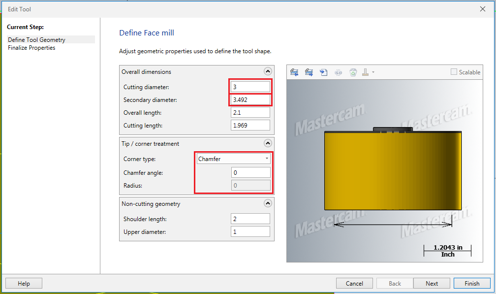
18 minutes ago, Roger said:
This also cut's below the surface.
It violates the surface due to the way the tool is drawn. Because you're not using the tool in a 2D plane this description won't work. Cutting Diameter is the inscribed circle of where the radii touch. Secondary is outside cutting edge. It's gouging because it's trying to use a mixture of both diameters for the 3D surface.

-
1
-
-
The plane settings, this is on a 3 axis?
-
You could create a surface from the solid, then edit the surface and create/manipulate the node points to appropriately represent the curvature. This would be time consuming and there may be a better way depending on how the model needs to be changed. If you do go this route I would lay out a grid pattern of points representing the curves, then create node points on the surface and bend it that way.
I know there is a simpler way to have points influence a surface, I watched a video on it recently. But can't remember where. If I find it I will post it here if you're interested.
-
1
-
-
I use it quite a bit. I sat down one day and drew up every holder in the shop. Any new holders that come through I also draw up. Like Old_Bear said, it doesn't support STP in the standalone. I've also been slowly adding most of the standard tooling we use. I can tell you that it is a bit faster then doing it through Mastercam after having to write up hundreds of tools and holders. Plus the ability to make assemblies without doing some weird stuff to get it working is great. I would recommend it.
-
12 minutes ago, Mark VIII said:
I think you are wrong Billb. The shank diameter is what it is using to control the cutting diameter. And, it does not make sense because they should have nothing to do with each other. The moral of the story is there is another MC error than needs to be fixed.Thanks for the time and effort you put into looking into this Bill. Maybe this is something Mastercam could look into changing in the future. For now I'll keep doing what I'm doing.
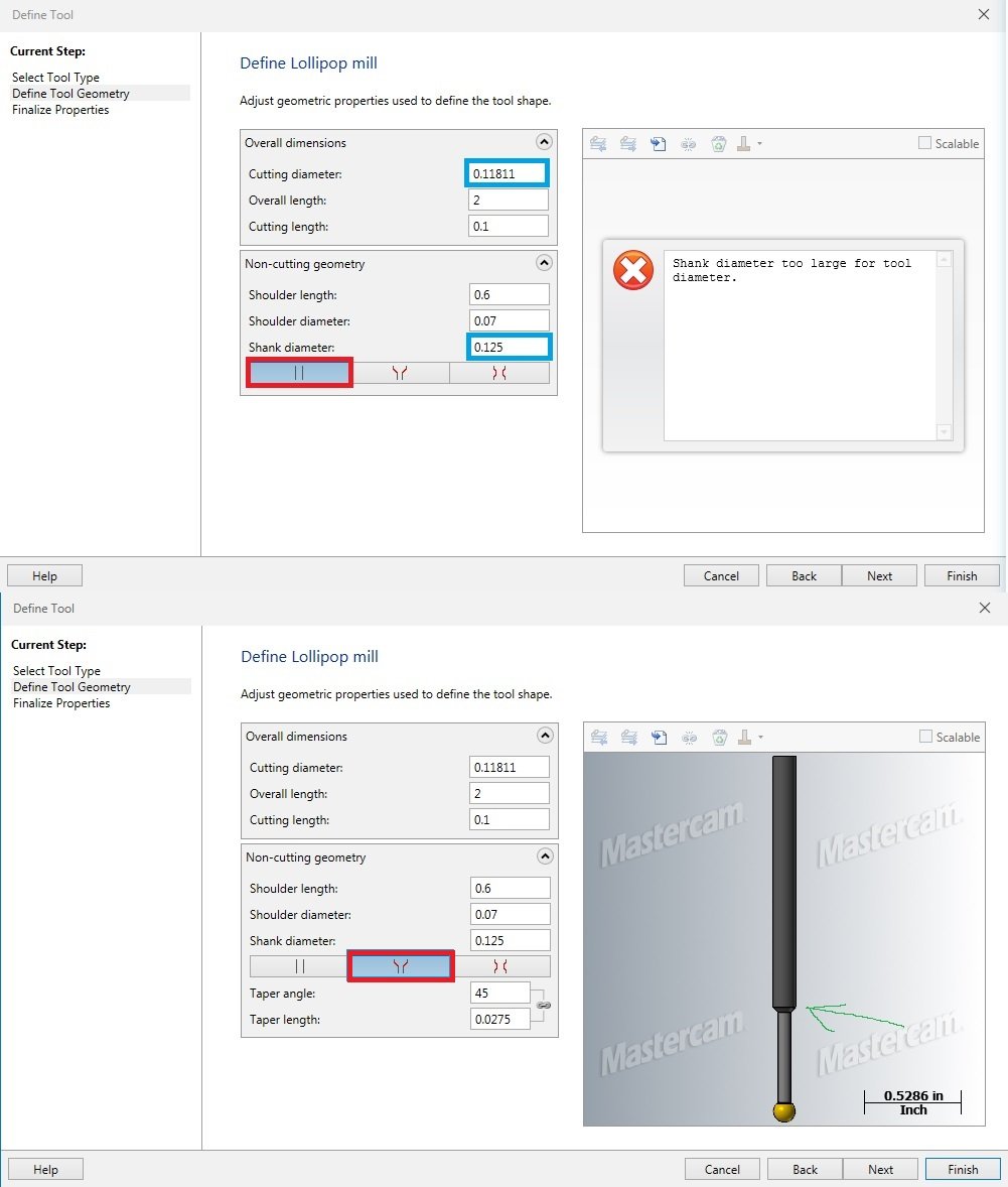
59 minutes ago, billb said:For the straight option, both the shank diameter and shoulder diameter are limited to the cutting diameter. To work around that rule, I was able to set up a tapered shape but use a big value (89 degrees) for the taper angle and set a really short shoulder length.
I hadn't thought of this. I'll have to try it out.
Thanks,
Caleb
-
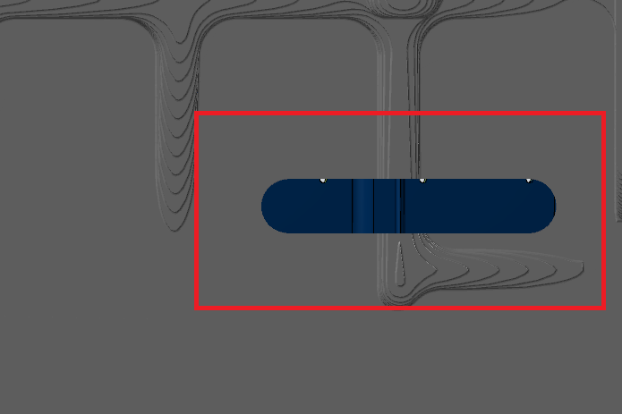
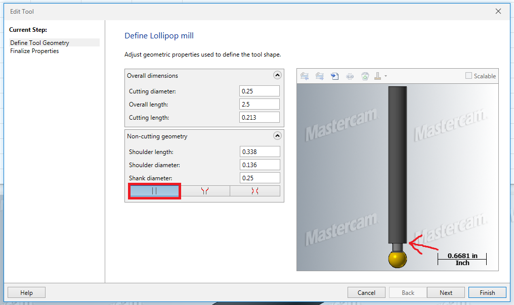
This photo shows the issues we are speaking of.
Top of photo shows a Straight Shank tool with the outline in blue being the problem.
Highlight in red shows only difference between the two tools.
Green arrow shows the taper that is the issue. With this taper described some paths error out.
As you can see there is an error in drawing the tool where the cutting diameter cannot be smaller then the shank size when using straight shanks.

-
13 hours ago, Mark VIII said:
When I do that it says "shank diameter is too large for tool diameter. The tool is a 3mm lollipop cut from a 1/8 shaft.
I've seen this problem before. So what's happening is the shank size is larger then the cutting diameter. This is not allowed for some reason. Try setting your shank diameter to 3mm also. Note on this that it only won't allow straight shank tools like this, tapered tools are fine to describe with larger shanks.
-
17 minutes ago, Mark VIII said:
The real problem is that there seems to no other way to describe your lollipop. If you put in a straight relief instead of a taper, tool editor alarms out.

Perhaps I don't understand the problem. Is this should we are talking about?
-
I had this warning just the other day. I figured out it has to do with the non-cutting geometry. The neck cannot end in a taper up to the shank size. It only calculates square shoulders. Don't ask me why, it seems really weird to me too.
-
You need to accept the points, then reopen the the parameters. The lower edit bar should now be lit up and ready to edit points.
-
8 minutes ago, Old_Bear said:
If you're using curves to drive, you can set the vector depth to a minus
Thanks. I couldn't find this exact setting, but starting playing with negative tolerance on the Multi Cuts page. I ended up putting a negative value under the "to" setting for tool shift. With "constant for each slice" selected. This did the trick.
-
1
-
-
Is there an easier way to make swarf mill cut deeper (Break Through) when only milling a wall with no floor? I've been manually drawing a floor suspended below the wall, but there must be an easier way to do this.
-
I'm seeing the same thing, have been since 2017. The second I launch "Define tool/holder." It only happens to me when the window is launched on my secondary screen. Regardless of where the tool manager is. If the define page launches on the primary screen it's fine. I can't even move the dialog to the secondary as it will wack out between "Define Tool Geo." and "Finalize Properties." Also note that moving from the secondary screen to the primary will screw it up pretty bad. It has to launch on the primary screen and stay there, otherwise it loses it's mind. This also happens on the "Edit Tool" page inside of Mastercam.
-
 1
1
-
Can't get a decent toolpath for rest roughing
in Industrial Forum
Posted
I dug into this a bit more. Sorry for the confusion. I reopened this and realized you were indeed using a 3D path. However, there are some problems with it.
First off: the problem with the path ramping into the part. The problem here is when using stock the containment boundary locks to "Stay Inside" this button is poorly named, and confused me for a long time. What you need to do is set the "compensation to:" to outside and type in an additional offset distance. Typically I type something fairly excessive into this field as it is only looking at stock, it won't actually make a path that is cutting air out in the middle of nowhere. This should fix all of the ramping as it can now start outside the part.
Second: Conventional will probably be faster for one reason. It is not running constant stepover like the 3D paths are. You said you were just milling right down the center of the part until you got to a depth where you needed to move over. So, radially your stepover was increasing with each z depth step. I'm not saying this method is bad. It just can't really be an apples to apples comparison.
Third: I don't believe any of the 3D paths are going to work the way you want them to. This is for one reason. They aren't really designed for variable radial loads, they're designed to maximize tool life. You could possibly 'break' one of the paths to get it to work. Or there might be in option in a legacy path that I don't know about.
Sorry this isn't that helpful.
Caleb