AWL304
-
Posts
45 -
Joined
-
Last visited
Content Type
Profiles
Forums
Downloads
Store
eMastercam Wiki
Blogs
Gallery
Events
Everything posted by AWL304
-
yep already did this thanks
-
this works except when it gets to the bottom of my surface or the " pattern to " line and the tool jumps around to the other side of the line.....still looking
-
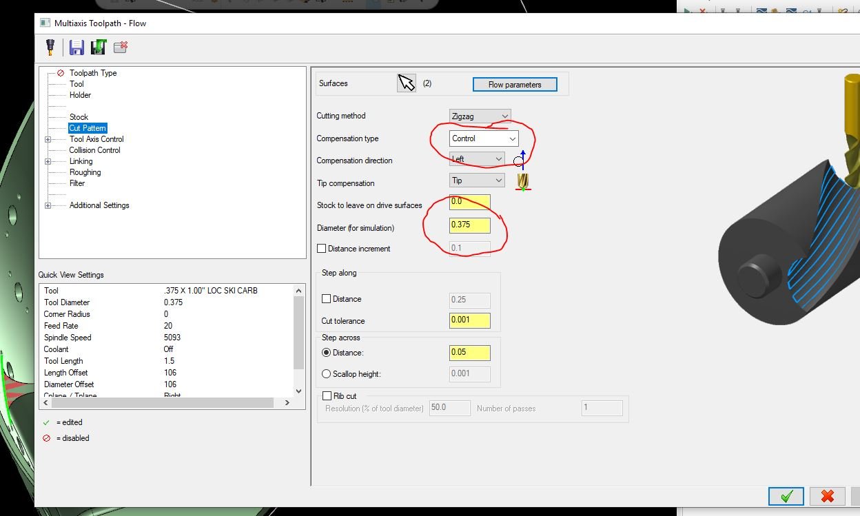
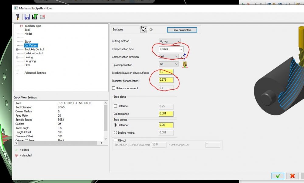
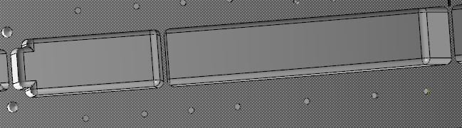
on a mazak integrex, i simply was hoping for a single tool path to go around this part ( portion attached ) and finish the tops of the ribs. But i can not find a way to have the tool path move to the edge of the tool, and not the center. the " diameter ( for simulation) " option seems to do nothing. can these paths not be used like this, and my post will not post a G41 for comp under any compensation option, is this possible? Yes i know I can do this with a gview tilted and simple 2-D path with transform but was hoping for one 5 axis path todo all. Thanks PATH TEST.mcam
-
IT does have G68 code. my issue is backplot showing the tool moving to centerline going into the G41 move to finish, but not posting G41 either
-
Not sure what im missing with this but, i want to simply helix down then comp on and finish the circle. but backplot shows the tool moving to centerline of the tool when going to finish the circle. i read in help that for backplot to show correctly there is the diameter ( for simulation) option when in control but it seems to do nothing. It doesnt post out a G41 for comp either??? yes it seems to work just fine when compensation is in computer but.
-
WORKED THANKS !!!
-
Since moving to MC2019 if saving a model from Mastercam 2019 as an .xt file and try to open it in Solidworks 2017 i get a "modeler version error"??? Anyone heard of this yet.
-
why are there two different swarf tool paths??
-
I'm Very new to multi axis tool paths, as seen in the picture attached, i have pockets wrapped around a diameter and need to rough/finish them. They have around +.130"/surface stk so.... i was hoping a swarf?? just wanted to go in and around the walls and then a constant scallop of some type for floor?? any suggestions would be appreciated!!
-
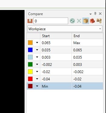
Is there a way to add more color options ( rows) in verify ??
-
i seen that works, except our shop uses "control" wear would causes problems, but....
-
I am trying to helix down roughing holes on a angle around an I.D. (also angled). Is there no way to have compensation turned on to "control", last move after helix ( comp move) runs the middle of my cutter (radius) around my circle at final depth. with compensation on "computer" it works great. but for finish adjustments, there would be none. What am i missing??
-
Invar 36 (Turning) (HEAT TREATED)
AWL304 replied to AWL304's topic in Machining, Tools, Cutting & Probing
ummmm not sure invar 36 per ASTM F1684-06 heat treated and annelled and now i get to final machined it so....... everything online has suggestions for high speed, im using carbide of course -
Any help with FEEDS/SPEEDS/DOP for turning application, sharper nose radius the better?? maybe comparable to Inconel??
-
is this what you are talking about (compensation)?? cant seem to be able to change option in lower left in compensation?
-
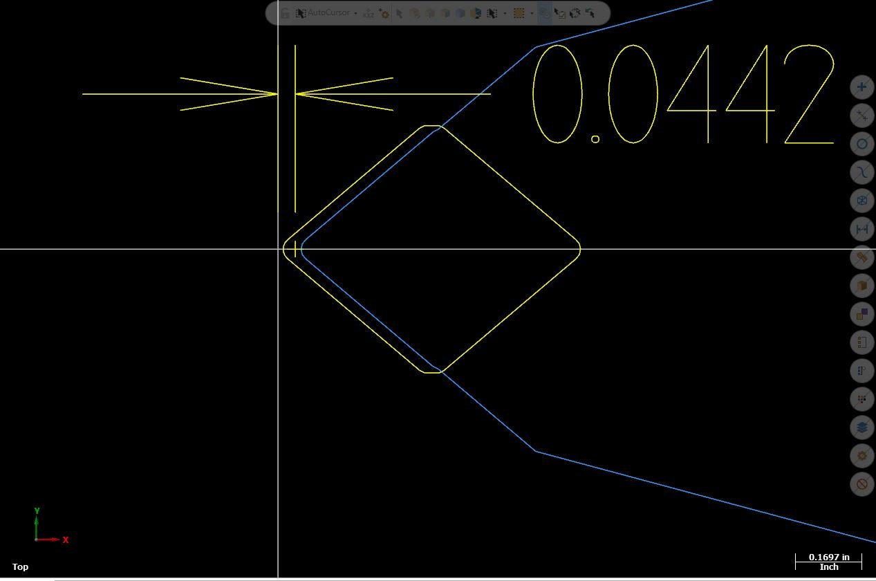
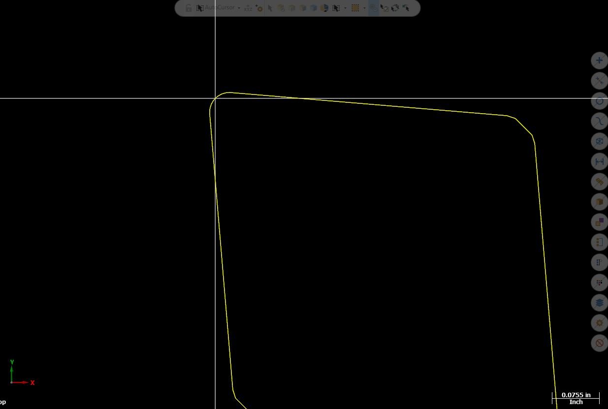
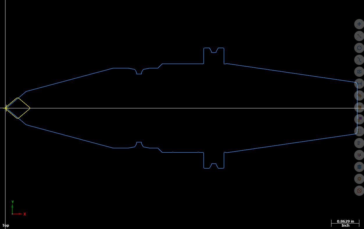
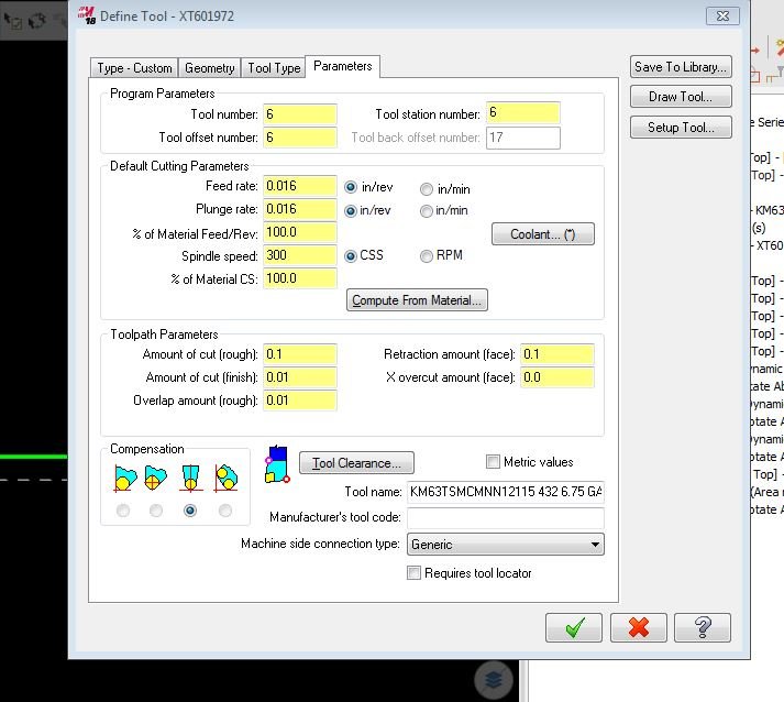
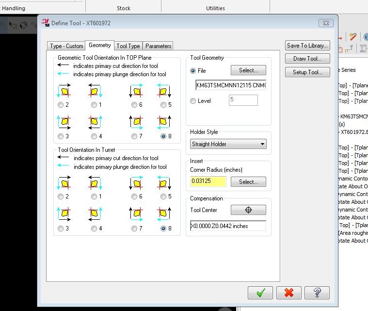
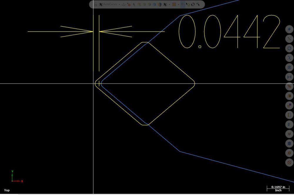
Well......... my only fix so far is to rotate my profile orientation to how i want it FIRST , then rotate it back to 0 deg about the origin, then rotate to 45 degrees in the tool path. both Z & X seem to get good numbers. just was wondering (hoping) if there was a way to do this in tool path or setup instead of having to draw all tools off center that i plan on rotating.
-
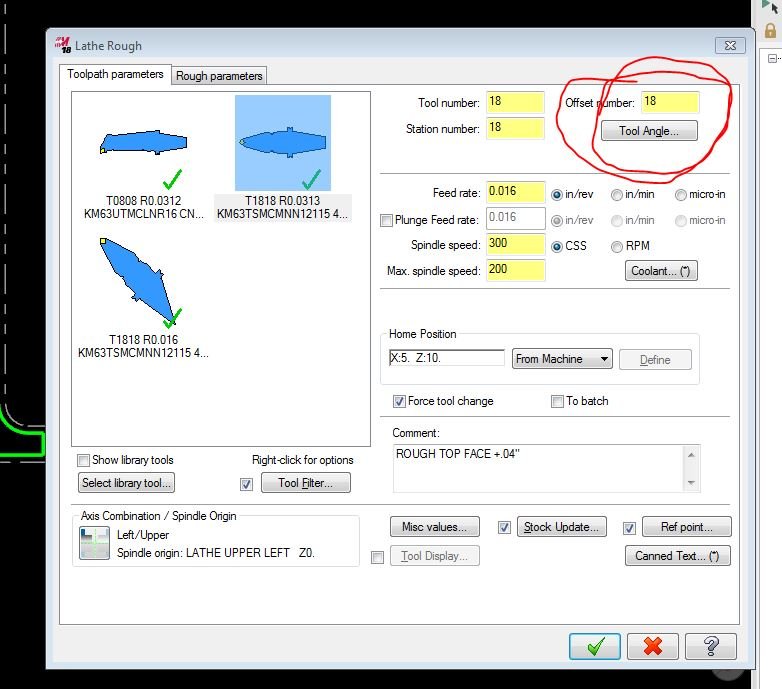
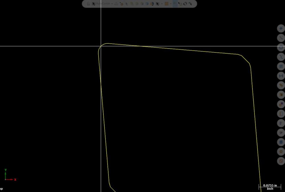
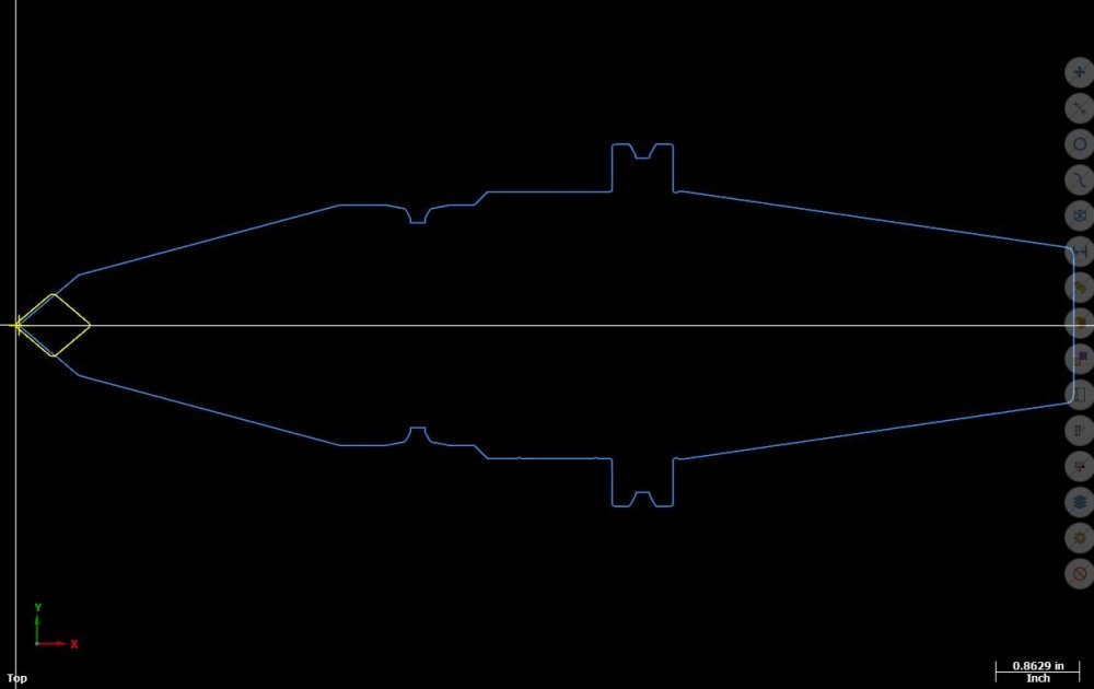
Programming a mazak intregrex, setting up a turning tool and want it to turn with the B axis @ 45 deg. problem is when i initially draw the profile to create the custom tool the profile needs to be straight (pic 3). I rotate the tool in the tool path with tool angle ( pic2) which works and post b45 but my Z numbers are off because its rotating the tool around origin not the center of the nose rad. am i missing something in tool path or do i need to draw the profile differently? FYI: i didnt draw profile on the angle first because then i cant get the B rotation to post out pic 1 is how far its off when rotated
-
yep only way i know of as of now also, this particular part has some odd shapes being cut out and was trying to avoid the time in dummy toolpaths. thanks
-
Are there any tricks to removing "chips" in your stk model display (inside mastercam not verify) from one operation to the next.