


JB7280
-
Posts
992 -
Joined
-
Last visited
-
Days Won
8
Content Type
Profiles
Forums
Downloads
Store
eMastercam Wiki
Blogs
Gallery
Events
Posts posted by JB7280
-
-
20 hours ago, crazy^millman said:
Can I ask a dumb question here? Why not use a 1/8 stub flute ball endmill if you are worried about rigidity? Use the bull in the floor, but use a smaller tool. Why are you trying to use in essence a size on size tool for such a feature? Back up and approach this differently and you will reduce run time and improve the quality of the work. Really want to be trick get a .375 endmill with a .062R made on it and plunge in one shot dwell after roughing with a .005 smaller tool.
Really for no other reason than the fact that I didn't want to add another tool just for that one feature. Also, the feature is inside of a pocket, so there are some limitations regarding reach. I edited the model, to just leave the feature I was asking a question about. However, as to your comment about using an essentially on size tool, that is creating a different issue, since I didn't anticipate the "cone" it's leaving on the .251" diameter floor. So I'll have to do something else.
Garr has a 3.8" endmill with a .060" corner rad, so I think I'll just go that route. I had thought about that, but we don't get enough money for these parts to warrant a special tool. Garr having one on the shelf makes it make a whole lot more sense.
Edit - Actually, scratch that. That's gonna have the same dish on the floor unless I have one made with a flat bottom. D'oh.
-
4 hours ago, gcode said:
I'll check that out Monday when I'm back at the shop. Thank you.
-
16 hours ago, ajmer said:
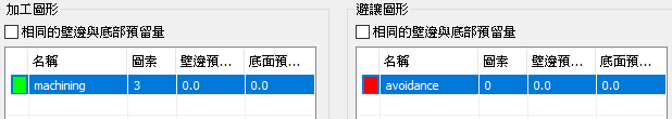
Looks like you removed the avoidance, and added a containment. Is the jagged path stemming from the software trying to avoid that face?
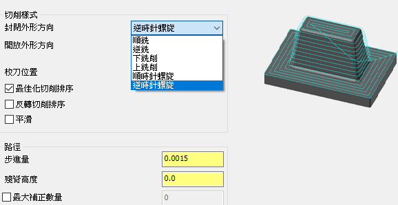
4 hours ago, bird2010 said:Equla Scallop...the step distance will be more even
That toolpath looks nice. I'll try it. Thank you.
-
58 minutes ago, #Rekd™ said:
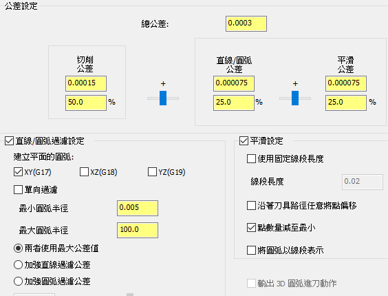
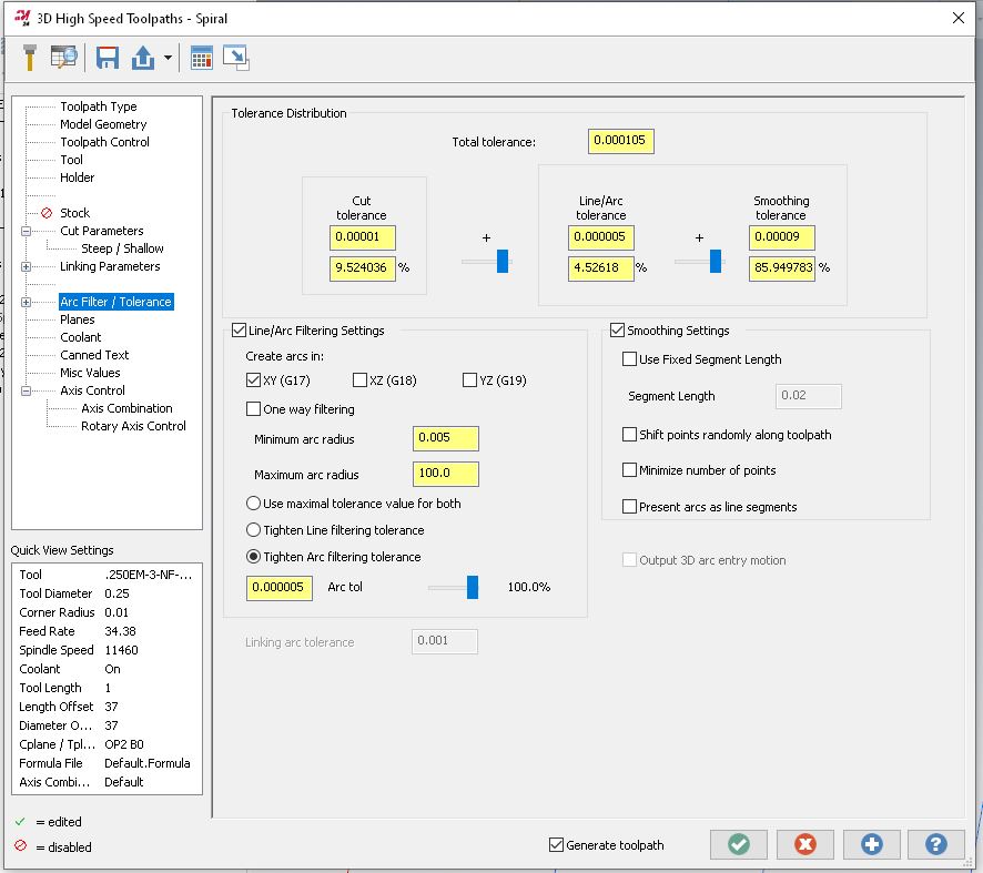
I changed the Arc Filter Settings and it seems better (took a while to generate though). Not sure how it will behave on the machine.
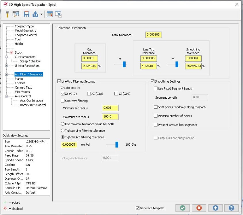
Thanks, I'll give those settings a shot on monday. At least I was on the right track, with the arc filter settings.
-
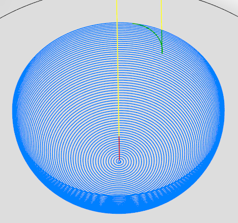
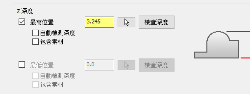
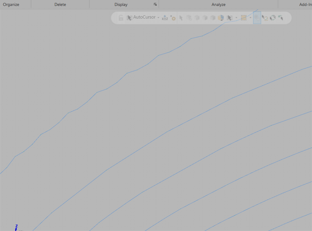
Can anyone help me figure out why this toolpath gets so jagged at the end? I've cleaned it up quite a bit by playing around with smoothing, in arc filters, but it still causes the machine to vibrate quite a bit at the end. Fyi, this is not the whole part. I cut the rest away so I could share the file.
Thank you.
https://drive.google.com/file/d/1vbAHIm2r20hf_NF5BITBQ0Is7ezl0djg/view?usp=sharing
-
35 minutes ago, nperry said:
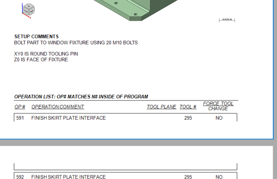
Got it. So it's been a while since I've messed with it in great depth, but your setup comments box, could you just make that vertically longer to force the beginning of your operation list to start on a new page?
Looks like I got it. I had tried that, but it wasn't working, initially. Looks like I had to make the whole "grid" area bigger, THEN increase the vertical length of that text box. Thank you for the help.
-
16 minutes ago, nperry said:
JB - I know I struggled with this in the past and if I remember correctly it had something to do with the boxes in the lower section of the docked panel on the right.
In the graphical section of active reports designer if you click the word "detail" it'll highlight that bar blue, then look at the menu to the bottom right. I could swear it was something in "behavior". Maybe try fiddling with the option "Keep Together".
Thanks for the suggestion. That was already set to True, and unfortunately, didn't seem to have any effect one way or the other.
-
Does anyone know how I can get the Operation section to start on the next page? I tried adding a PageBreak in between Setup Comments, and Operations, but when I do that, it wants to output a whole blank page.
-
59 minutes ago, Jake L said:
I think you end up with the same issue of not having the ability to specify you want the arc tangent thru the endpoint of the angled line. Unless there's something I'm missing?
Maybe I'm asking for too much all at once?
What if you extend the upper, angled line beyond the intersection point, so it's tangent, rather than an endpoint? I'm not on MC at the moment to try it, but it seems like it might like that better.
-
 1
1
-
-
17 hours ago, CEMENTHEAD said:
I would not recommend inspecting a part using the same machine that made said part. Been there, done that.
15 hours ago, Matthew Hajicek - Singularity said:Whether or not inspecting on the same machine that made the part will meet your needs, will depend on your needs. If you want to do it properly, you should meet the same bar as for other measurement methods; get your machine laser / ballbar calibrated, do a measurement repeatability and uncertainty test, etc., and make sure that your uncertainty is less than 1/10 your tightest tolerance. You can include measuring a gauge block / pin / ring as part of your inspection process to warn you of any calibration drift, thermal expansion issue, or other problem.
I 100% agree, that there are issues with inspecting the part, on the machine that made it. I've expressed that to management, and the engineering department is still being pushed to inspect parts on the machine. So, from this point, we'll just do what we can to inspect what actually makes sense.
-
For you guys who have used both, which do you prefer, The Cimco, or Renishaw add-ons for Mastercam?
Also, can someone explain the difference between inspection plus, and productivity plus? I think I've had them backwards for years.
-
1 hour ago, Aaron Eberhard said:
Oh man! I forgot to check MST's website. That makes perfect sense. Thanks! I love their tool holders.
I've never tried the toolholders, but I've heard great things.
-
20 hours ago, Aaron Eberhard said:
Who makes the smallest 90° head? I've got a feature that I'm trying to help a customer quote in a aerospace part (shocking!) that's a real PITA, only because of space restrictions. The machine itself is a standard Mazak 5 axis w/ a Cat 40.
I've went through my normal tooling catalogs, and it seems like the Kaiser/Big Daishawai BCV40-AG90-13-120 is the winner, at 25mm of clearance from the bottom of the housing to the centerline of the tool, but that'll mean I'm still hanging a 1/2" drill bit at least 5.75" out from this little thing.
Most of the other heads have at minimum 26mm of clearance, so we'll be hanging the tool out 6+ inches.
I don't have tolerances or anything yet, so this is all pretty preliminary, but I figured I'd ask who I'm overlooking.
Thanks!
Saw these guys at IMTS last year. They had some little baby right angle heads they were demo'ing. They're available to us through our mitsubishi rep.
-
 1
1
-
-
15 hours ago, Ulstermanone said:
-----Its a stupid idea in 2024 to be honest --------
You're right, and that's why they haven't used them for quite a few years now.
In all honesty, it sounds like your mind was made up from the beginning anyways. I'm curious though, what is this "new stuff" that's way too slow and doesn't work in "real life"??
-
2
-
-
This
 is wild!!
-
1
-
 3
3
-
-
19 hours ago, cruzila said:
Awesome Thanks!!!!!!
That's pretty much exactly how I do mine.
-
1
-
-
1 hour ago, Aaron Eberhard said:
I couldn't get it to work, either. I'm guessing that it's something to do with the 3 axis engine driving it? I'd send it in to [email protected].
What you can do to make it work is to switch to 3+2. With this part, you still get 3 axis only output, but it will generate.. However, it's still cutting on the "no go" area behind the ball, just like it is when you set the cutting length longer.
To be honest, though, with this cutter, I'm not sure what the desired results are in 3 axis.
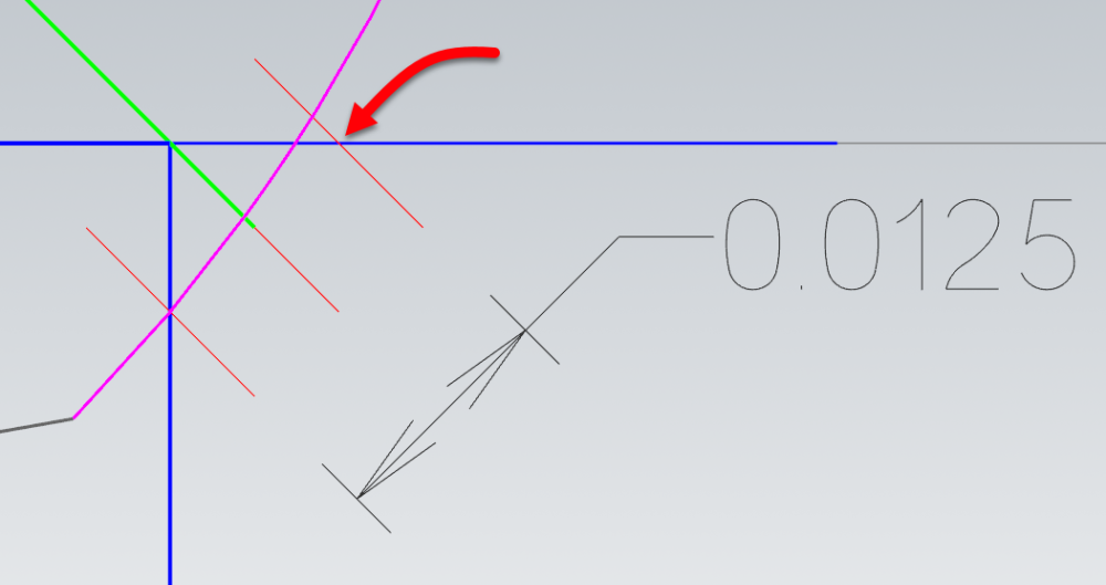
I mean, I know we want a perfect .0125" edge break cut like this:
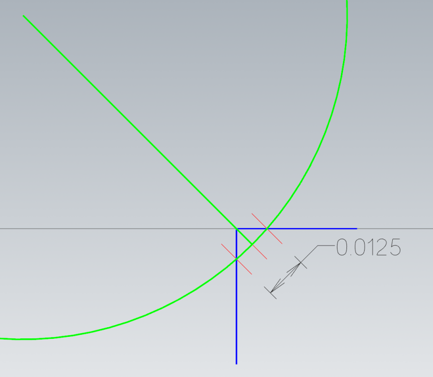
However, that requires the center of the ø.188 cutter to be perfectly 45° from the corner, tangent to the radius with that .0125 width.
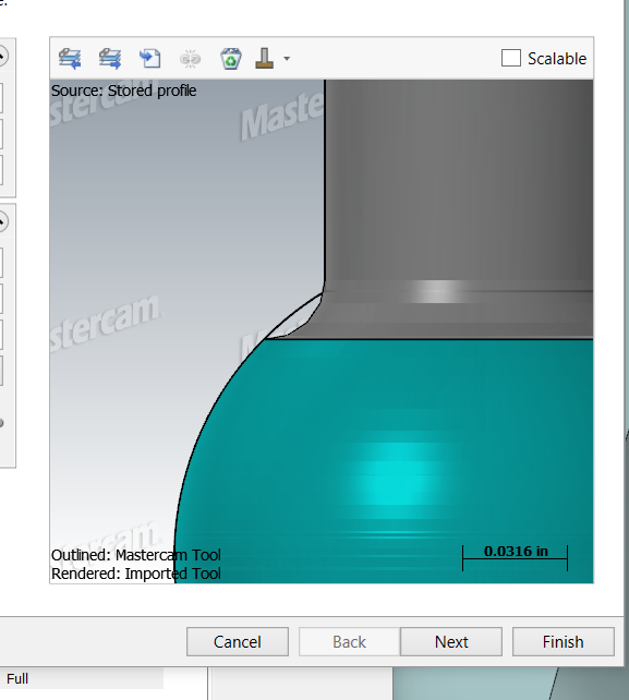
If we bring your tool profile over that, you get exactly what you see when you allow it to cut .17 length of cut, instead of .16 (remember that the toolpath will always calculate against a true ball, your custom profile is only for display/verification purposes):
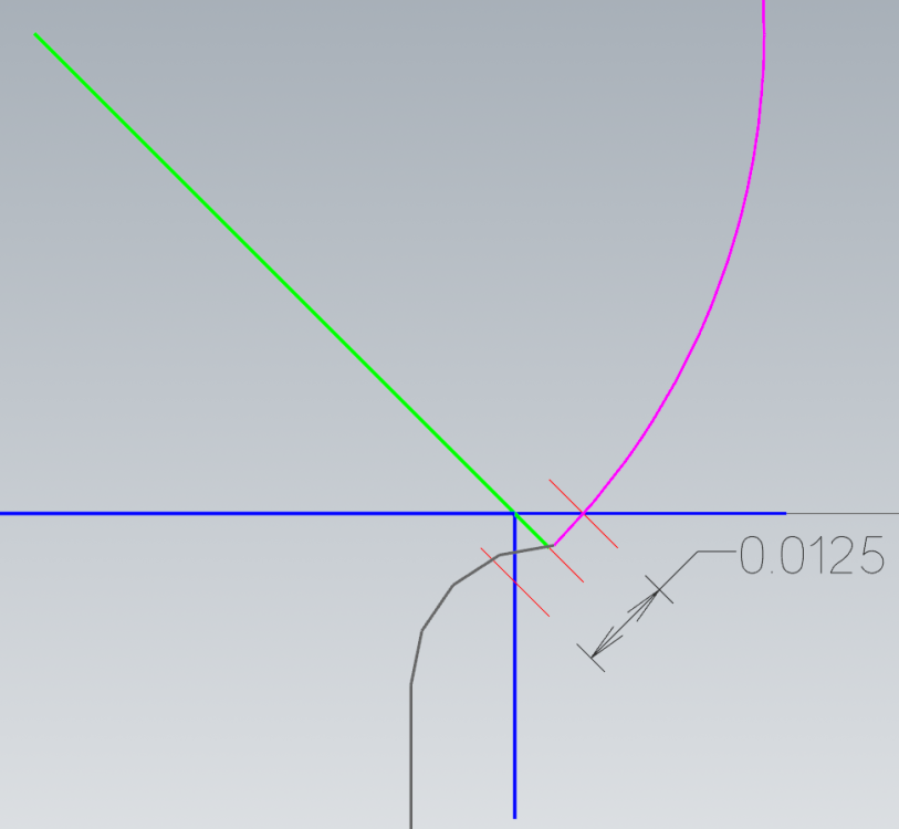
If you try to slide your tool down so it's not cutting with the back part of it, then it becomes impossible to maintain a constant width:
I would expect it to work, though, with a constant depth (you'll have an uneven width on the two sides, of course), but that doesn't work either.
I'd guess that this is an enhancement, that the algorithm team at ModuleWorks would have to handle specifically.
I think you'll need to drive this one manually and report it for future improvements.
That makes sense. So it's trying to make it a perfect 45, but the tool profile doesn't allow for it.
I can just do a normal contour, since I'm not really looking for a specific chamfer. Just a deburr edge break.
Also, I was not aware that Mastercam sees it as a true ball, despite the profile, so I appreciate that bit of knowledge.
-
1
-
-
On 2/23/2024 at 3:59 PM, Aaron Eberhard said:
Can you post a file?
I made one toolpath with the cut length set to .16", per Harvey's website. Then another one with an extra .01" added on, so it would generate a toolpath.
https://drive.google.com/file/d/1v2mQA36a01resceaPnPiBnz0HMhcrjHL/view?usp=sharing
-
51 minutes ago, Aaron Eberhard said:
Can you post a file?
Not of this part. But I'll make something similar later to recreate it. I've left the shop, but Ill try to post it when I get home.
-
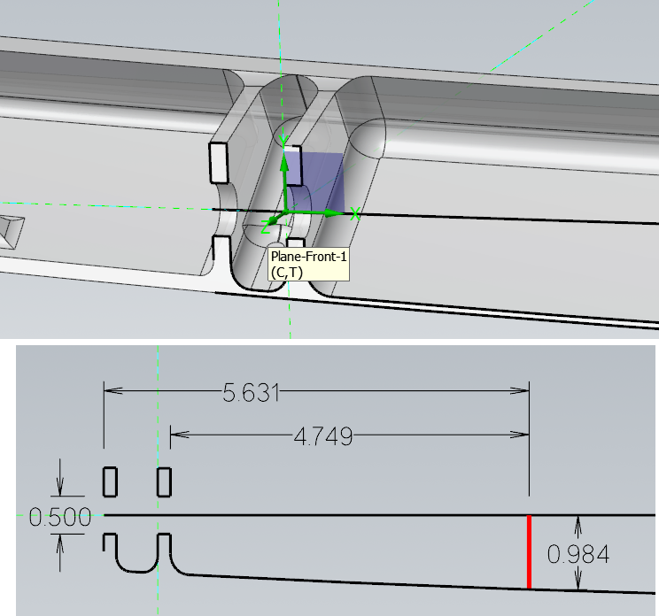
Is it possible to control the contact point in a Multiaxis Deburr (being used in 3 axis) toolpath? The reason I ask, is I'm having some trouble. About a year ago, I made this post;
Where I learned that sometimes adding extra length of cut will get you better results in a deburr toolpath. However, I have a lollipop mill that looks like this;
The only way for it to be able to calculate a toolpath is to extend the length of cut, but then it wants to try to cut in that internal radius area. I know I could just do it the old way, with a contour, but I'm just wondering if there's a way to make this work properly.
-
48 minutes ago, ajmer said:
i used an mpmaster i had
i changed this
search for and uncomment this line
# sav_rot_on_x = rot_on_x #Uncomment this line to output rotary axis value even when it's not used
then at the end of ptlchg0$ i added a pfcout on that line
ptlchg0$ #Call from NCI null tool change (tool number repeats)was this
else,
[
pbld, n$, sgabsinc, [if not(index), pwcs], pfxout, pfyout, pfzout, pcout, e$
]
]i changed to
else,
[
pbld, n$, sgabsinc, [if not(index), pwcs], pfcout, pfxout, pfyout, pfzout, pcout, e$
]
]gave me this output
N5 G00 G17 G20 G40 G80 G90
N10 G91 G28 Z0.
N15 (COMPENSATION TYPE - COMPUTER)
N20 T239 M06 ( 1/2 FLAT ENDMILL)
N25 (MAX - Z.25)
N30 (MIN - Z0.)
N35 G00 G17 G90 G54 B0. X-.25 Y.5 S1069 M03
N40 G43 H239 Z.25
N45 Z.2
N50 G94 G01 Z0. F6.42
N55 X-.75
N60 G03 X-1.25 Y0. I0. J-.5
N65 X1.25 I1.25 J0.
N70 X-1.25 I-1.25 J0.
N75 X-.75 Y-.5 I.5 J0.
N80 G01 X-.25
N85 Z.2
N90 G00 Z.25
N95 G55 B0. X-.25 Y.5 Z.25
N100 Z.2
N105 G01 Z0.
N110 X-.75
N115 G03 X-1.25 Y0. I0. J-.5
N120 X1.25 I1.25 J0.
N125 X-1.25 I-1.25 J0.
N130 X-.75 Y-.5 I.5 J0.
N135 G01 X-.25
N140 Z.2
N145 G00 Z.25
N150 M05
N155 G91 G28 Z0.
N160 G28 Y0. B0Close, and gives me some hope. I need retract, and unclamp/clamp comments. I wish I knew more about editing posts. But that's hopeful at least.
-
18 minutes ago, SuperHoneyBadger said:
Are the two B0 offsets always the same relative to one another?
I would consider the first as B0 and the second as B6 (or whatever) and when they share a WCS, you know it will rotate between them.
Also on my horz, I need to force a tool change in between rotations for the same tool, or it will skip over the B call - might try that out. You'll be certain to get a retract then as well.
In CAM, yes, they're the same. In the machine, they're slightly different from each other. So I need it to correct when going between the two offsets. But yea, I'll probably do a force tool change for now, unfortunately.
11 minutes ago, JParis said:I built a whole section of logic that handles this for me...I have a jump height set in the MR's....on any offset change or rotation I output the jump height...
No "Force Tool Change" required.
Haha, I have no idea what that means, but I assumed something like that is what's necessary, which is beyond my knowledge level. Might have to get a post made for this.
-
3 hours ago, crazy^millman said:
With rotated planes and a correctly configure post then it should output the rotations you want. Really a couple different ways to control this. Can you make a dummy file with a couple toolpaths to use as example.
I would like for it to post Z retract, Rotary Unlock, B positioning move, and Rotary lock after the N2 line. To correct for "fixture error" I feel crazy, because people, including Mastercam Tech Support seem to think I'm doing something wild, lol. But I am 100% certain I've done this fairly simply in other CAM softwares.
3 hours ago, gcode said:Without having a copy of the file I can't recommend a good solution
I would just post a dummy drill cycle at a different B location that punches a hole in a safe place in the sky.
After posting, just delete the dummy drilling toolpath and you are good to go
I did something similar, temporarily, but the powers that be (aka management) likes to have files that post out, 100% ready to run.
https://drive.google.com/file/d/1iUOKIpRsN_3lvTRoej_nlYAyfBDuc1ot/view?usp=sharing
-
2 hours ago, crazy^millman said:
With rotated planes and a correctly configure post then it should output the rotations you want. Really a couple different ways to control this. Can you make a dummy file with a couple toolpaths to use as example.
That's the issue Ron, I think. The planes aren't technically rotated, but they are different work offsets. I'll make a dummy file in a moment.


"Jagged" Spiral toolpath
in Industrial Forum
Posted
Not necessarily a tool change. Just trying to avoid adding another tool to the magazine, as its almost full and this machine has a bunch of jobs on it that run pretty much constantly. I ended up just adding a 1/8" ball mill though.