Jake L
-
Posts
335 -
Joined
-
Last visited
-
Days Won
8
Content Type
Profiles
Forums
Downloads
Store
eMastercam Wiki
Blogs
Gallery
Events
Everything posted by Jake L
-
I have what I hope will be quick question. I'm looking into starting to program chooks for a variety of reasons, and I can't seem to find a solid answer to this question. My fear is I'm going to dive into learning C or C++ then realize I need the opposite language. Any help or advice is much appreciated. If more information is needed please let me know. Not sure if it matters but I'm running Mastercam 2022.
-
That's awesome to hear. It took me a few minutes to figure that out when I started using this toolpath. What about the "Home / Ref. Points" tab? Instead of just having a clearance plane (or clearance area) will we also get an option to send the machine to a specified retract or home position after it finishes the toolpath? Or is this option already available and I just don't know it? We use reference points all the time if we want to have a retract height, a clearance height, and a large clearance height. (The large clearance height is usually used anytime we need to rotate the part in the 4th or 5th axis once the toolpath is finished). The only three work arounds I can currently see to this problem are to put a point toolpath in to retract the tool. Have a toolpath as shown in the picture which seems like a waste of time, especially on a larger part. Or, use the clearance blend spline, which is usually but not always the ideal method.
-
I now have a follow up question. On the same toolpath, with the same file, the purple transition moves are broken into line segments. Is there a way to have Mastercam automatically make those arc moves? I would rather a large arc move that travels a little farther, than segments. Some of the machines read the segments slow so they can only travel so fast on those moves. I would rather an arc so the machine just has one move and can go as fast as it can go. Usually I would look for that in the toolpath in the Arc Filter / Tolerance tab but the deburr toolpath does not contain that tab. I understand I could have the machine retract and rapid each time I have to change positions, but that is also slow because then I have to rapid out of the part every time.
-
That's definitely an option I'll keep in mind. It won't work for the particular project I'm on, but I'm sure I will run into this issue again. Thank you.
-
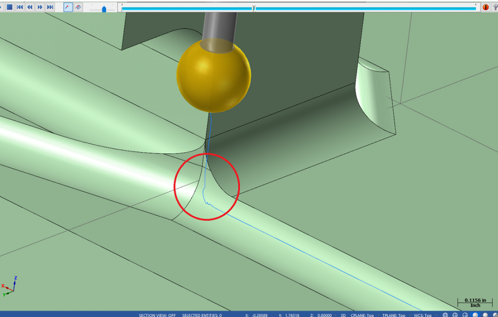
Recently I have started regularly using the multiaxis deburr toolpath on many of my parts. Most of my parts are run on some form of a 3 axis vertical machine. As shown in the screenshot, when the toolpath gets to a complex edge it seems to have a hard time figuring out a smooth path. It ends up producing a very jagged toolpath which takes a lot of extra time for the machine to run. I tried playing with the surface quality tolerance, and the chaining tolerance but that only seems to help a little. I can never seem to eliminate all of the roughness. My question is, is there a way to smooth out those corners? Or is it just a matter of being a complex edge and the software can only do so much with it? I have attached a mastercam file as an example. Please ignore speeds and feeds and other technicalities as I'm just trying to display the toolpath issues. I am running Mastercam 2022 and the tool I'm looking to use is a 1/4 diameter lollipop tool. If more information is needed please let me know, and thanks in advance for any help anyone can give on this topic. Deburr_Toolpath.mcam
-
Thank you so much. Apparently I was limited to 3 posts a day because I just signed up, but this was figured out yesterday morning. It was mostly me not fully understanding what I was trying to do and also not fully understanding how Mastercam worked. I ended up copying, at least for the most part, the mcam file JParis posted. The biggest mistake was not drawing in the whole tower. I thought that was an unnecessary step and that I could just skip it to save time. Turns out, while it is technically unnecessary, it makes understanding this concept much more difficult. Oh well, live and learn I guess. Thank you again for the quick and helpful responses. I'm sure this won't be my last post here. I'll be back the next time I can't solve a problem.
-
I'm going to sound like a complete beginner here but what's HMC? My pickup for the part is; X0 / Y0 centerline of part, Z0 / B0 face of stock. Because the single part program has no rotations, my zeros don't have to be point of rotation. Because I have two separate work offsets I thought I didn't need to define and use a second T&C plane in Mastercam because the 180 rotation will be put in the offsets at the machine. Just to make sure I'm understanding what you did let me put it in my own words. You moved the wireframe off the origin and gave it a new T&C plane. This allows Mastercam to recognize the rotation you called in the transform toolpath, and update the B0 when G55 is called. My question is this, in this scenario, would the zeros that you have to input into the machine be the point of rotation (Mastercam origin) or would the zeros be the T&C plane origin? My head is starting to spin a little but I think I'm on the verge of understanding all of this.
-
Thanks for the quick response. I feel as though I may be misunderstanding how translate works. When I told translate to automatically increment the work offset number I figured it would define a new T&C plane for me behind the scenes and I wouldn't have to touch my planes. I was also under the impression that when a new work offset was called up there would automatically be a safety B0 move. Secondly, the two parts I'm trying to machine have separate pickups (the face of each part will be B0 in the program). I could be miscommunicating that information, or misunderstanding that. Another solution for my problem is; if I posted the code for a single part, then changed all the G54's to G55's then I would be able to use those two programs to run the two parts. However, doing so would waste a lot of cycle time because all my tool changes would have to happen twice. I attached a mock program of a very simplified version of what I'm trying to accomplish. Saftey_Move_After_Work_Offset_Change.mcam
-
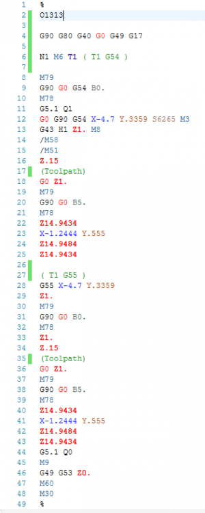
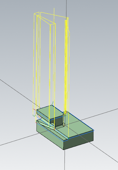
I just finished programming a part and we want to run two parts at a time on the same machine with two separate work offsets (G54, G55). Because of the large number of toolpaths, I ended up using a transform toolpath for each tool to duplicating the toolpaths, and I just incremented the offset number by 1. This seemed to work great except for one thing, my parts are running in a 4 axis horizontal machine, and the two parts are setup on opposite sides of a tower. I posted the g-code, and when the program switched to G55 there was no B0 safety move like there usually is at the start of each tool. Because of this, all I have done is make a program that will ghost pass every toolpath at the same position on the same part. I'm hoping there is an easy fix here I but have yet to find it. One thing that did work was putting a position point at the end of each group of toolpaths, and giving that a rotation move. This caused there to be a rotation move right before calling up G55 (to B5. or any specified number) which, in turn, caused the machine to reorient to G55 B0 when it called G55. This will work it just seems like a very large work around for a problem that I'm hoping has a simple solution. I'm running Mastercam 2021. The machine is a horizontal 4-axis Smart SX4000 with a Fanuc 31i control. The post is an in house post but I tried a stock post and encountered the same problem so I don't think that's the issue. Attached is the original G-code as well as the G-code for the work around. Any help is much appreciated, I've been stuck on this one for a few days now. I ended up just putting in B moves by hand so at least the machine can be running while I figure this out, but I hate editing the G-code by hand. Hopefully I have included everything needed.