


Jake L
-
Posts
340 -
Joined
-
Last visited
-
Days Won
8
Content Type
Profiles
Forums
Downloads
Store
eMastercam Wiki
Blogs
Gallery
Events
Posts posted by Jake L
-
-
30 minutes ago, Kyle F said:
my wet cardboard box of a haas
LOL
-
On 11/1/2023 at 1:50 PM, Grapes said:
Let me know if this works. Surface Finish Flowline.ZIP
I found the file but the lines show up for me, can't seem to replicate the issue.
-
Not sure what the overall process looks like but on our 4-axis HMC's we always program a single work offset from POR. The only time our pickup isn't POR is if there's no rotations, then we usually do some type of 3-axis pickup. I always figured programming from POR was industry standard, maybe not?
We also use tooling balls if we need them.
-
 1
1
-
-
Our setup sheets say "out of holder" but when we talk about it "stickout" is the term I hear most often. I'm in NE USA.
-
On 11/2/2023 at 9:25 AM, #Rekd™ said:
@Aaron Eberhard When would you include the "origin" and when wouldn't you?
Always learning from this forum, awesome!!!
If you want the operator to be able to set a new WCS origin then you need to include the origin. Ex. if you have 3 parts in 3 different vises you don't want to have to setup the vises and stops perfectly to one another (a single pickup for all 3 parts) so including the origin in the transform allows the machinist to set each vise separately (G54, G55, G56).
OP wanted to cut the same pocket 4 times on the same part. You don't need a new pickup for every pocket so you don't want to transform your origin in that case.
IMHO transform is super powerful and super lacking at the same time.
On 11/2/2023 at 11:04 AM, #Rekd™ said:It might be a good idea to have a thread on the Industrial Forum pinned to the top on Transform Toolpath.
Some toolpaths (axis substitution) don't work with Rotate so you need to use Translate - Coordinate - Delta
+1 to this idea. I use translate somewhat frequently but not frequently enough to learn all the ins and outs. There's so many options and different combinations of buttons that I tend to end up using the trial and error method until I get the output I want.
-
I just went thru this. Here is the hardware I ended up with, if you want me to go into more detail on any of this let me know.
RAM - 96GB
GPU - NVIDIA RTX A4000 16GB
CPU - Intel i9-14900k liquid cooled & overclocked
Here's some links if you want to do more reading:
https://mcamnw.com/how-to-optimize-your-pc-for-mastercam/
-
 1
1
-
-
2 minutes ago, Notar said:
Intel(R) Core(TM) i9-10885H CPU @ 2.40GHz 2.40 GHz
NVIDIA Quadro T2000
Windows 10 Pro
32GB Ram
What issues are you looking to see improved? Graphics lagging, Toolpath regen, dialogs opening, all of the above?
What type of work / models do you see most? How much of your Mcam files are multiaxis vs 2D?
Do you typically have other software open? Outlook, web browsers?
-
What are your current spec?
-
4 minutes ago, Sigurd said:
There's a zip file in my post.
I only see a .jpg in the zip file
-
1 minute ago, JParis said:
Surface Finish Blend would be my first goto....second I would create a flat track surface above the are you are looking to cut Surface Finish Flowline the flat track and then project that tool path down onto the surfaces..
Both of these are much less complex than my idea. I love this forum
-
Any chance you can upload a file so we can all play with the same thing?
My first thought was unified project with multi pass. I'm sure there's many ways to accomplish this.
-
- Popular Post
- Popular Post
23 hours ago, AHarrison1 said:Use Scallop height instead of Distance.
Wanted to do an in depth explanation of this because it took me a long time to figure out when to use stepover vs scallop and why.
Tool center and tool contact point are two different things. The toolpath lines we see in backplot are where the center of the tool will be.
When surfacing around a radius and driving by stepover, the center of the tool must take larger steps to keep the stepover at the contact point consistent.
In these pictures you can see when driving the toolpath based on the stepover, the stepover around the radius stays consistent at .099-.100, but the tool center stepover is much larger around .298.
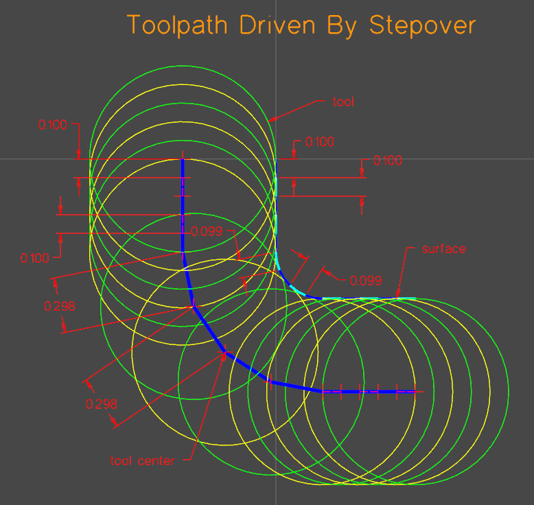
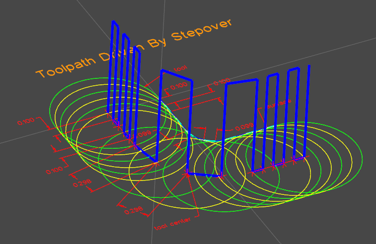
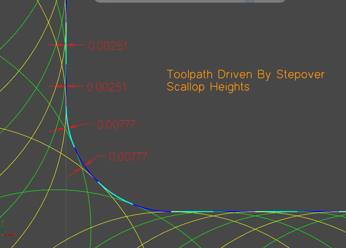
An unexpected consequence of using stepover is the scallops around a radius will be bigger or smaller than scallops left on flat surface.

When using scallop to drive the toolpath, you tell Mastercam you care more about the height of the scallop than the stepover. This causes the stepover of the contact point to shrink around outside radii and grow around inside radii.
Dropbox Link To File and Pictures (MC2023)
Please correct me if there are any mistakes in this explanation. I think I have a solid understanding of this concept but there's always more to learn. Hope this helps!
-
3
-
12
-
Shooting in the dark without a file...
Usually I'll see this collision when the tool hits the stock while plunging in preparation for the entry motion.
Try increasing z clearance on the entry motion and see if that fixes it.
-
1
-
-
22 hours ago, CoonDogWillie said:
how to judge and decide which of the many 2 or 3 D strategies MS has available is the one I should select
Super dependent on part geometry, but this is generally roughly what I end up with in a typical file. Most of my work is 3 + 1 aerospace parts.
50% operations are 2D contour - it's hard to stray from this toolpath because of how much control it gives you. The downside is most of the time you have to create additional geometry to chain.
15% 2D or 3D dynamic (OptiRough)
15% Drill/Counterbore
20% other (2D Pocket, 2D Area Mill, Flowline, Deburr, Unified, etc.)
Most of the toolpaths in Mastercam are very application specific. For example there are cases where 3D Spiral is the perfect toolpath for the job, but 9 times out of 10 Flowline or Unified will do just as well.
The way I learned was trial and error. The toolpaths pictures give an idea of what the toolpath is used for, so using that you can start to make guesses and build experience.
-
1 minute ago, XXDALIXX said:
It's sometimes challenging to convince decision-makers, even when the potential time and cost savings are clear.
Too true
-
 2
2
-
-
1 minute ago, XXDALIXX said:
Unfortunately, our company doesn't want to spend any additional money, so we're looking for a solution that can be implemented without extra expenses.
You just got to prove the return on investment.
Ex. if I spend 3 hours a week typing tools into a tool sheet and getting X+ or something similar can bring that 3 hrs to 5 minutes... how many weeks before the product pays for itself and from then on it's saving money at no cost.
-
2
-
-
Graphics Cards - is there recommendations for how much memory Mastercam / Vericut wants? Is an NVIDIA RTX4000 16GB a good choice or should I up the memory? I see it starts to get pricey real quick going up from here.
I would like this gpu to be able to handle a MC 500MB file, with 300 operations, 20 stock models, and Vericut be able to handle the posted code from this file with no interruptions or stuttering.
-
30 minutes ago, gcode said:
Depending on it's age and origin, your post may need some work to support tool inspection.
3 hours ago, JParis said:THe plinout section is almost all modern posts has a sketched portion to do just that
plinout         #Output to NC of linear movement - feed
      if sub_is_active & absinc$ = 0, result = force(xabs, yabs)
      pcan1, pbld, n$, sgfeed, sgplane, `sgcode, sgabsinc, pccdia,
        pxout, pyout, pzout, pcout, [if motst$, feed], strcantext, pscool, e$
      if rpd_typ$ = 7, ptool_insp #Tool Inspection Point
the if rpd_typ7$ is the trigger line that sends it to this section
ptool_insp   #Tool Inspection Point Customization Required
      #Modify following line to customize tool inspection points
      pcool_off #Coolant off before tool inspection
      sav_absinc = absinc$
      absinc$ = one
      pbld, n$, sm05, e$ #Spindle off
      pbld, n$, sm00,"(CAUTION POST GENERATING MOTION FOR TOOL INSPECTION)", e$
      pbld, n$, *sgabsinc, *sg28ref, "Z0.", scoolant, e$
      pbld, n$, *sg28ref, "X0.", "Y0.", e$
      pbld, n$, sm00, "(INSPECT TOOL)", e$
      absinc$ = sav_absinc
      pbld, n$, *sgcode, *sgabsinc, pwcs, *xabs, *yabs, *speed, *spindle, pgear, e$
      pinsp_cool_on #Coolant on after tool inspection
      pbld, n$, sg43, *tlngno$, *zabs, scoolant, e$
You can edit that as needed to get what you need.
This reply above is exactly what was in my post. I did a couple mods to position the tool where I want but it looks like the post is behaving correctly. If we end up using tool inspect more down the road I'll know where to come back to.
The issue I was having is my tool stays in the cut for most of the toolpath so MC never finds a safe spot to retract for a tool inspect. For this particular case I ended up just splitting up a 2D dynamic operation into 4 separate ops. I can see tool inspect being much more useful when you aren't milling a square block onto a square piece of stock. Tool inspect is a new tool I'm happy to now have in my toolbelt, just not the right tool for this particular case.
Again, thanks for all the replies and insights. Always more to learn
-
2
-
-
https://www.emastercam.com/forums/topic/106592-custom-setup-sheets-vs-mastercam-ones/
Checkout this post, a ton of good info in there
-
2
-
-
1 hour ago, crazy^millman said:
Two of the best on here.
24 minutes ago, Jobnt said:You're so humble.

Agree with both of these. The skill and experience on this forum always amazes me.
-
Follow up question, is there any tricks to force the tool to exit the cut periodically?
The tool inspection is awesome but my tool is in the cut for the first 90% of the toolpath. As soon as it comes out of the cut to loop back around it retracts for a tool inspect, but by then it's been in the cut for 50min of the 60min total.
I think I may be trying to find that elusive easy button here.
My first thought was to use two separate dynamic mill ops. Both would create a retract after every pass allowing the tool inspect to happen at any of these retracts. The biggest thing I don't like is exiting and entering the cut every single cut, I'd rather do it every 5 or 10 passes than every one. Please see dropbox pictures
-
Man you guys are quick in the morning. Thanks for the responses. Exactly what I was looking for.
I kept searching "tool check" instead of "tool inspection" that explains why I couldn't find it.
-
I seem to remember reading something about this but can't remember the specifics.
I have a 2D Dynamic toolpath running for over an hour, every 15 minutes I'd like to stop the machine to clear chips and check the tool, then reenter the cut where I left off. The only way I can think to do this is chop up my dynamic mill op into 4 separate ops and force tool change each op. Is there a way to do this automatically so I don't need to create multiple ops and new wireframe for each?
My post is a slightly modified MPFAN. MC2023
-
10 minutes ago, Aaron Eberhard said:
Jake - Feel free to give me a call, as this sort of thing is easier to explain on the phone, but basically, it's really hard to create a perfect toolpath that will utilize 100% of all available processors. Really hard. Keep in mind that a highway at 100% utilization is a grid-lock....
Stock models are a great example of something that can't really be multithreaded effectively. You have to take one toolpath and step through it to see material removed. One step at at time. There are some tricks being played when there's logical sections that can be established, but you always have to balance something like that with how much effort to spend pre-processing to see what can be split up vs. just getting through the work.
At the end of the day, clock speed is still king for a lot of this sort of stuff.
Funny, I was just reading one of your responses from 2020 - https://www.emastercam.com/forums/topic/100265-nvme-drive/
Any chance you could PM me contact info? I tried to PM you but it said you couldn't receive messages. I'd love to have a conversation on this topic.
Suggestions for milling Titanium
in Industrial Forum
Posted
Is that before or after Jesus turns water to wine?
Genuinely curious about this, where are you getting this 55% rule from?