BehindYou
-
Posts
46 -
Joined
-
Last visited
Content Type
Profiles
Forums
Downloads
Store
eMastercam Wiki
Blogs
Gallery
Events
Everything posted by BehindYou
-
 Greetings Poolrod2. Yes there is a way. The most easiest way: Send me your post so i can change it. Generate some random gcode and mark what should be removed /added or i can guide you through so you can do it yourself . when you decide which way you want please PM. Other then that please check if your post ends with .pst or .psb if you have both files then most likely you can't edit your post file. if you have more questions feel free to ask Kind regards Ivan
 -
What you need is in 2000's parameters from there you can get info about the tools tcr$ is varable which will give you tool tip radius
-
Did it work?
-
Greetings @mirek1017 Before I go on, Whatever you do in your post it's on your own responsibility. Follow this steps and you will have output which you want, related with insert width for groove tools 1. Create format statement if you don't have it already fs2 25 1.4 1.2lt #Decimal, absolute, 4/3 trailing 2. Create new variable: fmt "Groove Insert Width = " 25 groove_width # Tool width for programming ( "Groove Insert Width = " you can change the name how ever you like) 3. Go to pparameter$ postblock (there is one more way which doesn't require this) add : if prmcode$ = 20102, groove_width = rparsngl(sparameter$, 4) # Capture insert width for grooving tools make sure you will follow the order of the numbers (just to keep it tidy) 4. Go to ltlchg$ #Toolchange, lathe postblock Search for Comment$ predefined variable, now past this either above or under comment$ variable ( you decide) if opcode$ = 103, sopen_prn, sline, groove_width, sline, sclose_prn, e$ what it will do is this if opcode$ is equal to 103 (103 means Groove) print ( | value which is stored in the groove_width variable | ) new line ( e$ means new line) other then that add new strings in your post scomm_str : "(" scomm_end : ")" sline : " | " now this is our : ( | Groove Insert Width = 2.00 | ) ( #6. Operation type - Plunge rough; also, chained grooves | ) just because I pasted if opcode$ = 103, sopen_prn, sline, groove_width, sline, sclose_prn, e$ above predefined comment$ variable our output is before ( #6. Operation type - Plunge rough; also, chained grooves | ) This is your personal decision how you want it. I hope this can help you. If you need more help/information's feel free to contact me. kind regards Ivan.
-
yes
-
Greetings @mirek1017 To get information about your grooving insert you should use 20102 parameter and you will get insert width. *Use rparsngl function This is my output (T44 | OD GROOVE LEFT - NARROW | D44 | INSERT - Width = 3.00 ) (#6.Operation type - Plunge rough; also, chained grooves | ) ( | VC = S115 mm/min | ) ( | MAX RPM = S2000 RPM | ) ( | Feedrate = 0.10 mm/rev | ) (==========================================================) Kind regards Ivan Žugec
-
You should provide your code so i can take a look. Because this isn't coming with MPLFAN.pst as default. Kind regards Ivan
-
Greetings @mirek1017 Go to pl_retract postblock in your post and change to this pl_retract #Retract tool based on next tool gcode, lathe (see ptoolend) cc_pos$ = zero if home_type = one, [ pmap_home #Get home position, xabs ps_inc_calc #Set inc. pbld, n$, psccomp, e$ pcan1, pbld, n$, *sgcode, pfxout, pfyout, pfzout, *toolno, e$ pbld, n$, pnullstop, strcantext, e$ ] else, [ #Retract to reference return pbld, n$, `sgcode, psccomp, e$ if home_type = m_one, pbld, n$, *toolno, e$ pcan1, pbld, n$, *sg28ref, "U0.", [if y_axis_mch, "V0."], "W0.", change to this ---->pcan1, pbld, n$, *sg28ref, "W0." pnullstop, strcantext, e$ cutoff_proc = zero #Reset flag if we are retracted if home_type > m_one, pbld, n$, *toolno, e$ ] this example is from MPLFAN.pts file your post may look little bit different. Logic which I am using is like this pl_retract #Retract tool based on next tool gcode, lathe (see ptoolend) Here you can change output before tool change cc_pos$ = zero if home_type = one, [ pmap_home #Get home position, xabs ps_inc_calc #Set inc. pbld, n$, psccomp, e$ pcan1, pbld, n$, *sgcode, pfxout, pfyout, pfzout, *toolno, e$ pbld, n$, pnullstop, strcantext, e$ ] else, [ #Retract to reference return---- pbld, n$, `sgcode, psccomp, e$ if home_type = m_one, pbld, n$, *toolno, e$ if spindle_stop = 1, [ pcan1, pbld, n$, pnullstop, strcantext, e$ pcan1, pbld, n$, [if scoolant = sm08, sm09, e$], strcantext, e$ plathe_refpoint, ] else, [ pcan1, pbld, n$, [if scoolant = sm08, sm09, e$], strcantext, e$ plathe_refpoint ] if spindle_stop > 1, "Invalid input of Miscellaneous value #8 it should be between 0 and 2 ! ", e$ # pnullstop, pscool, strcantext, e$ # you can se M9 here before the tool change cutoff_proc = zero #Reset flag if we are retracted if tl_offset = 1, [ if t$ <> tloffno$, tloffno$ = t$ ] toolno = t$ * 100 + tloffno$ if home_type > m_one, pbld, n$, *toolno, e$ ] plathe_refpoint #Custom Tool Retract for Lathe if refpoint_lathe = 1, n$, *sg28ref, "U0.", "W0.", e$ else, [ if refpoint_lathe = 0, n$, *sg28ref, "U0.", e$ n$, *sg28ref, "W0.", e$ else, [ n$, *sg28ref, "U0.", [if y_axis_mch, "V0."], "W0.", e$ ] ] if refpoint_lathe > 2, "Invalid input of Miscellaneous value #6 it should be between 0 and 2 ! ", e$ Hope this can help you and guide you on the right path. Kind regards Ivan
-
Lathe sub spindle posting as Z axis
BehindYou replied to tkelch27's topic in Post Processor Development Forum
Greeting @tkelch27 You should check variables which are related with stock/part transfer. For example if variable stck_final_z$ is giving you final Z position of your transfer operation, check Format Assignments and Initializations section in your post fmt "Z" 2 stck_init_z$ fmt "Z" 2 stck_final_z$ fmt "Z" 2 stck_chuk_st_z$ fmt "X" 2 stck_chuk_st_x$ fmt "B" 2 stck_chuk_end_z$ fmt "X" 2 stck_chuk_end_x$ fmt "B" 3 stck_chuk_st_dz$ fmt "U" 3 stck_chuk_st_dx$ fmt "B" 3 stck_chuk_end_dz$ fmt "U" 3 stck_chuk_end_dx$ fmt "Z" 2 stck_clear$ fmt "X" 2 stck_tool_x$ fmt "Z" 2 stck_grip$ if you want to learn meaning of the predefined variables I can share you dropbox link where you can download all the MasterCam related files in our example if I change fmt "Z" 2 stck_init_z$ to fmt "B" 2 stck_init_z$ My output will be B120. instead of Z120. -
Angle Calculation between vectors
BehindYou replied to BehindYou's topic in Post Processor Development Forum
@H.tom where have you been few days ago with this solution ? At the end both codes are giving same result only difference is your code is short and simple and mine is long and complex -
Greetings @Hemkant HEMKANT This is how I did in my post Go in prpm postblock and search for sgfeed string pbld, n$, [if nc_system_type = 0, *sgfeed], [if nc_system_type >= 1, *sgfeed_b] *sg97, *speed, "P12" , *spindle_m, e$ What I did above? If I change variable nc_system_type to value 1 it will output G99 if I keep value 0 output is G98 ( depends which G-system code I am using) N170 G98 G97 S2315 P12 M03 Or just change string sg98 # -------------------------------------------------------------------------- # Feed mode G code selection sg98 : "G98" #UPM Fanuc A Group of G-code sg99 : "G99" #UPR Fanuc A Group of G-code sgfeed : "" #Target string fstrsel sg98 ipr_actv$ sgfeed 2 -1 # -------------------------------------------------------------------------- # Feed mode G code selection sg98_b : "G94" #UPM Fanuc B Group of G-code sg99_b : "G95" #UPR Fanuc B Group of G-code sgfeed_b : "" #Target string fstrsel sg98_b ipr_actv$ sgfeed_b 2 -1 # -------------------------------------------------------------------------- But you should provide more information's how your output should look like for the milling mode and turning mode so I can give you accurate info where/what and how to change. Once again example above is how I did for my machine (Controller (Fanuc) machine (puma 5100))) Kind regards Ivan Žugec
-
Angle Calculation between vectors
BehindYou replied to BehindYou's topic in Post Processor Development Forum
FINALLY!!! I had some retarded mistake in the calculation. Not it works perfectly it's showing only 90 and 180 degree angles. Sometimes you just can't see what is in front of your eyes -
Angle Calculation between vectors
BehindYou replied to BehindYou's topic in Post Processor Development Forum
Greetings @Zaffin_D I did how you told me to do and the angles looks ok for now, except they are wrong I went deep in this calculation and I just cant collect myself (doing the normal job and editing my post) Can you check what I did wrong this time? If you like I can share full code so you can test yourself if you like, v1x = (prv_x$ - x$) * 2 # x-component of vector v1 v1z = prv_z$ - z$ # z-component of vector v1 v2x = (nextx$ - x$) * 2 # x-component of vector v2 v2z = nextz$ - z$ # z-component of vector v2 v1_magnitude_squared = v1x * v1x + v1z * v1z v2_magnitude_squared = v2x * v2x + v2z * v2z v1_magnitude = sqrt(abs(v1_magnitude_squared)) v2_magnitude = sqrt(abs(v2_magnitude_squared)) # Normalize vectors v1_normalized_x = v1x / v1_magnitude v1_normalized_z = v1z / v1_magnitude v2_normalized_x = v2x / v2_magnitude v2_normalized_z = v2z / v2_magnitude # Calculate dot product with normalized vectors dot_product_normalized = (v1_normalized_x * v2_normalized_x) + (v1_normalized_z * v2_normalized_z) # Check if dot product and magnitude product are within valid range if dot_product_normalized >= m_one & dot_product_normalized <= 1 & v1_magnitude > 0 & v2_magnitude > 0, [ # Calculate angle between the vectors in radians angle_rad = acos(dot_product_normalized) # Convert angle from radians to degrees angle_deg = angle_rad * 180.0 / pi$ ] else, [ # Calculate the angle using atan2 for orthogonal vectors if v2z = 0 | v1z = 0, v2z = 1, v1z = 1 angle_rad_1 = v2x / v2z # Calculate the tangent of the angle between v1 and v2 angle_rad_2 = acos(angle_rad_1) # Calculate the angle between v1 and v2 in radians angle_rad_3 = v1x / v1z # Calculate the tangent of the angle between v1 and v2 angle_rad_4 = acos(angle_rad_3) # Calculate the angle between v1 and v2 in radians angle_rad = angle_rad_2 - angle_rad_4 # Calculate the angle between v1 and v2 in radians ] # Ensure the angle is within the range [0, 2*pi$) # Check if dot product is very close to zero if abs(dot_product_normalized) < angle_tolerance, angle_deg = 90.0 # Vectors are orthogonal else, [ # Check if dot product is less than -1 + 1e-10 0.0000000001 if dot_product_normalized < m_one + angle_tolerance, angle_deg = 180.0 # Vectors are 180 degrees apart ] while angle_rad >= 2 * pi$, [ angle_rad = angle_rad - (2 * pi$) ] # Convert the angle from radians to degrees angle_deg = angle_rad * 180.0 / pi$ # Initialize the direction variables with unknown direction #sdirection_x = sundirection #sdirection_z = sundirection # Determine the direction of the vector for x-axis if v1x < 0 & v2x > 0, sdirection_x = sudirection else, [ if v1x > 0 & v2x < 0, sdirection_x = sddirection ] sdirection_x, e$ # Determine the direction of the vector for z-axis if v1z > 0 & v2z < 0, sdirection_z = sldirection else, [ if v1z < 0 & v2z > 0, sdirection_z = srdirection ] sdirection_z, e$ # Output the angle in degrees and the direction angle_deg, e$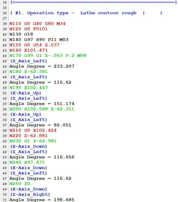
-
Angle Calculation between vectors
BehindYou replied to BehindYou's topic in Post Processor Development Forum
@Zaffin_D thank you for the advice. I will check/test it out on monday, at the moment i dont have cam licence at home . -
Angle Calculation between vectors
BehindYou replied to BehindYou's topic in Post Processor Development Forum
what exactly do you mean with "to normalize" ? -
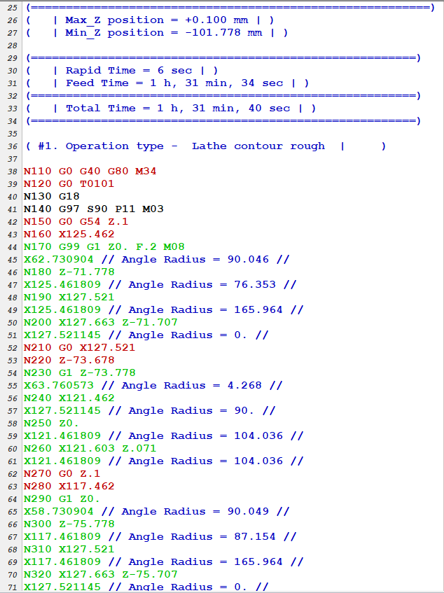
Greetings everyone, In the code which is below I am doing angle calculating ( more like checking if the angle is 180 or 90 degree) Why? When I am doing rough zig-zag motion I have problems with chips at the walls ( check pic below) So what I am trying to do is to check if I have 90 degree angles and convert the to arc, just to avoid nasty long chips. I know I can do this kind of turning with normal operation, but I want to do something different. Code which will convert corners to arcs is ready now the only issue is checking the angles. If you have any advice it would be nice, if you see mistake in the code please tell me and guide me on the right path, information's about how to calculate dot product and magnitude product I got it from : https://en.wikipedia.org/wiki/Dot_product https://en.wikipedia.org/wiki/Cross_product Other then that there is an issue with acos, this Sh** always wants to be between -1 and 1..... pcalculate_angle v1x = (prv_x$ - x$) * 2 # x-component of vector v1 v1z = prv_z$ - z$ # z-component of vector v1 v2x = (nextx$ - x$) * 2 # x-component of vector v2 v2z = nextz$ - z$ # z-component of vector v2 # Calculate dot product and magnitude product of the vectors if v2z = 0 | v1z = 0, v2z = 1, v1z = 1 # Check if either v2z or v1z is zero and set them to 1 to avoid division by zero dot_product = (v1x * v2x) + (v1z * v2z) # Calculate the dot product of v1 and v2 if dot_product = 0, dot_product = 1 # If the dot product is zero, set it to 1 to avoid division by zero v1_magnitude_squared = v1x * v1x + v1z * v1z # Calculate the squared magnitude of v1 v2_magnitude_squared = v2x * v2x + v2z * v2z # Calculate the squared magnitude of v2 v1_magnitude = sqrt(v1_magnitude_squared) # Calculate the magnitude of v1 v2_magnitude = sqrt(v2_magnitude_squared) # Calculate the magnitude of v2 angle_rad_1 = dot_product / (v1_magnitude * v2_magnitude) # Calculate the cosine of the angle between v1 and v2 angle_rad = acos(angle_rad_1) # Calculate the angle between v1 and v2 in radians # Convert angle from radians to degrees angle_deg = angle_rad * 180.0 / pi$ "//", *angle_rad, "//", e$ # Check if dot product and magnitude product are within valid range if dot_product >= m_one & dot_product <= 1 & v1_magnitude > 0 & v2_magnitude > 0, [ # Calculate angle between the vectors in radians angle_rad_1 = dot_product / (v1_magnitude * v2_magnitude) angle_rad = acos(angle_rad_1) #"//", *angle_rad, "//", e$ # Convert angle from radians to degrees angle_deg = angle_rad * 180.0 / pi$ ] else, [ # Calculate the angle using atan2 for orthogonal vectors if v2z = 0 | v1z = 0, v2z = 1, v1z = 1 # Check if either v2z or v1z is zero and set them to 1 to avoid division by zero angle_rad_1 = v2x / v2z # Calculate the tangent of the angle between v1 and v2 angle_rad_2 = acos(angle_rad_1) # Calculate the angle between v1 and v2 in radians angle_rad_3 = v1x / v1z # Calculate the tangent of the angle between v1 and v2 angle_rad_4 = acos(angle_rad_3) # Calculate the angle between v1 and v2 in radians angle_rad = angle_rad_2 - angle_rad_4 # Calculate the angle between v1 and v2 in radians #"//", *angle_rad, "//", e$ # Ensure the angle is within the range [0, 2*pi) if angle_rad < 0, angle_rad = angle_rad + 2 * pi$ # Convert the angle from radians to degrees angle_deg = angle_rad * 180.0 / pi$ #*angle_rad, e$ #*angle_deg, e$ ] for now output looks like this:


-
Moving tool offset cancel
BehindYou replied to littlerob's topic in Post Processor Development Forum
@Aufreisen Search for " toolno = t$ * 100 + tloffno$ " in your post, and just remove that line @littlerob Find toolno = t$ * 100 + tloffno$ and remove tloffno$ Your output will be like this T0200 Use debugger to locate where is your tool output and where is your reference point output. After that just place tool output above your reference point output. If you want I can send you example. Kind regards Ivan. -
Greetings Mirek1017 If you like there is another way to remove peck2$ and peckclr$ First create new variable peck_cle : 0 (or choose some other name) Now go to your peck postblock in my case lpack$ (if mill mpack$) and add pcan1, pbld, *sgdrlref, pgdrlout, pxout, pyout, pzout, prdrlout, peck1$, [if peck_cle = 1, peck2$, peckclr$], dwell$, pffr, strcantext, e$ What it means, if your peck_cle variable = 1 you will get output for peck2$ which is subsequent peck and for peckcir$ which is Peck clearance If you don't want output for for those two things just set value of peck_cle variable to 0 If you have more questions feel free to ask. Kind regards