


Guess_who
-
Posts
336 -
Joined
-
Last visited
-
Days Won
6
Content Type
Profiles
Forums
Downloads
Store
eMastercam Wiki
Blogs
Gallery
Events
Posts posted by Guess_who
-
-
8 minutes ago, ahaslam said:
I'm a little confused. Are you just looking for a Macro to find the center of a sphere? Will you be running vectors parallel to an axis (such as in z) and are your machines a table-table configuration? Also, how close will the repositioning of the tooling ball be? +/- .125?
Actually, I'm looking for the math to solve for center of a sphere given 4 points that can be done using a macro in the machine. I'm capable of writing the macro, I just don't understand the math.
Yes, our configuration is table/table. As far as the positioning, I would do it similar to how the MX-520 does it. We place the sphere at approximately the 12 O'Clock position. Step one would be to find the location and set an offset, then do the probe checks.
-
Check out the Chook, Nethook sub-forum.
https://www.emastercam.com/forums/forum/10-mastercam-c-hook-net-hook-and-vbscript-development/
-
56 minutes ago, jlw™ said:
that might be kinda small to get the results you need. worth trying tho.
give me a few days (if you got it) and I'll send you something.
We have plenty of time. This is more of a learning experience, but something that can be useful. And I guess I didn't think of the small sample size. I guess I could run 2 sets of 4 and average.
43 minutes ago, huskermcdoogle said:So, I am sure you already know this, but it is all about tracking the error vector. If you don't mind it taking a little bit longer execution wise, do it in two steps. This way you are only doing one axis transformation at a time which is easy to accomplish long hand. No need to get all fancy and do it with only 4 measured points. Find the tilt, then find the rotate. Use a pocket measure function on the waistline of the sphere, single surface the top, then interate until you pass a repeating trap that checks to make sure your measurement repeats to a given tolerance. With a strain gage probe, I would guess you will be good on the second go around. If you want to make sure it is perfect, index the spindle 180 and hit it again to take out probe error, by averaging the two results. Then move onto the next point.
That's pretty much what we do now, but we don't really have it automated. It takes a while to run, but probably more accurate. I just noticed the MX-520 only uses a few points and thought, hey, I wanna do that.
-
Still didn't fix it? That's weird. I think your reseller would be your best bet. Like Jparis said, your control def isn't properly connected to your machine def or something.
-
Under the MACHINE tab, Click control definition, the on the left click Misc. int/real values. Integer 1 will probably be set to 0 or 1, change it to 2. and try posting again.
-
Post the example of the code, my guess is in your parameters page - misc values. Usually there is one that can be set to use g92's.
-
We would use a tooling ball.
-
They don't change by much. But the operator will notice some positions not holding. Could be someone bumped the fixture or something. Anyway, to determine if we lost centerline, we have to do it the old fashioned way. Which we could automate, but I was thinking we should be able to do it with just 4 points.
We actually already own Axisset that we use in our Matsuura MX520. That's where I got the idea. I already ran it past the boss to buy more. But we have 5 more Makino D500's 5th axis machines and two Jidic 5th axis coming in a month or so. Starts to get expensive.
Plus it's sounds fun to try to get it to work.

-
I'm looking for some help writing a Fanuc Macro to calculate the center X, Y, Z position of a sphere using 4 points in space on a 5th axis Makino D500
I found some information online, but the formulas I'm finding use matrix math. Which I know very little about. My goal it to get the math worked out to put it in a fanuc macro long hand. There is no matrix function in Fanuc 31i as far as I know.
The point of this is to give the operator the ability to run this program and adjust the centerline of the 5th axis swing using parameters 19700, 19701, etc.
And help is appreciated.
Thanks
-
33 minutes ago, 5th Axis CGI said:
2018 not 2017.
That explains it. Thanks.
Do you know where I can find info on it? I look through the what's new doc, but it didn't jump out at me.
-
So I read somewhere that starting in MC2017 we can change the bitmaps associated with drilling cycles. Can anyone point in the right direction where to change this?
-
Well just ask if you need any help. BTW, I see you're from Rochester. I lived there up until I was 21. Where about's are you? I used to live in Churchville-Chili, and Gates Chili.
-
We do it similar to David, except we have a rotation macro we use. Basically, it knows where centerline of table is and it recalculates and changes G59 whenever it rotates the machine and the switches the active offset to G59.
-
Is that on a 40 hr week?
Not in Az. I've been salary for 15 years, and been working 48 the whole time. My company is pretty relaxed, so 48 is no big deal.
-
 1
1
-
-
In Arizona, I think most experience programmers can pull between 70k and 90k, with the top 10% making an easy 100k or maybe more.
-
1
-
-
Can I ask why do you want to prevent this? This can cause some issues. For example, if you're at 350 deg, and want to take the long way around to 10 deg, how would the machine know which way to go? With wind up, it's never a problem
But, that being said, in the control definition there is a section under the c-axis that looks like this.

Or there is a section in the post that looks similar to this;
sang_output : 0 #Angle output options, secondary
#0 = Normal angle output
#1 = Signed absolute output, 0 - 360
#2 = Implied shortest direction absolute output, 0 - 360 -
So you can create another variable with the correct preceding characters and transfer to that when needed. Something like below.
Format section:
fmt "B" 11 cabs #C axis position
fmt "PC=" 11 cabs_calc #C axis position calculation
fmt "PA=" 11 aabs_calc #A axis position calculation
Then before you use it you can;
cabs_calc = cabs ( this transfer the value into cabs_calc with the PC= preceding letters )
aabs_calc = ???? (this does the same thing for the A axis but I wasn't sure how your axis is defined, hence the ????)
Then;
pcan1, pbld, n$, "CALL 0088", *cabs_calc, *aabs_calc, "PH=1 PP=100", e$
Does this make sense?
There are other ways to accomplish this, and many people on here that are way better at this than me. Maybe they can give you another way or explain this better.
-
Hi guys!
I'm looking for a possibility to break my angle parameters in the postprocessor (p_out, s_out) to get the output value of it only in degrees without the letters C or A.
For example: G0 C45. A54.736 <----- with the post line like this (pcan1, pbld, n$, *sg00,*p_out, *s_out, e$)
G0 45. 54.736 <----- with the post line like this (??????????????)
There is no NCI output for them, I think they are calculated inside encrypted PSB file (correct me please), so how I can get does values as an output to my NC code, I need to put them to my angle recalculation macros line for 5x mill.
Thank you for any advices!
I'm not sure why you would want that, but you need to change the format. For example, the below example will change the 'cabs' variable to NOT post a 'B' prior to it.
fmt "B" 11 cabs #C axis position
To
fmt "" 11 cabs #C axis position
-
Well I think it's working as intended. If it kicked people off when other logged in, then you would constantly get kicked out when someone else logged in. And I know of know way of kicking someone out remotely.
But there is a software that can at least identify who is logged in. We use it here. It's called nethasp Monitor and it can be downloaded from the mastercam site.
-
Paul,
Thank you for the fix
Added this and all fixed.
commvar$ : -1 #Disable automatic conversion of numeric comments
-
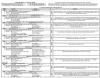
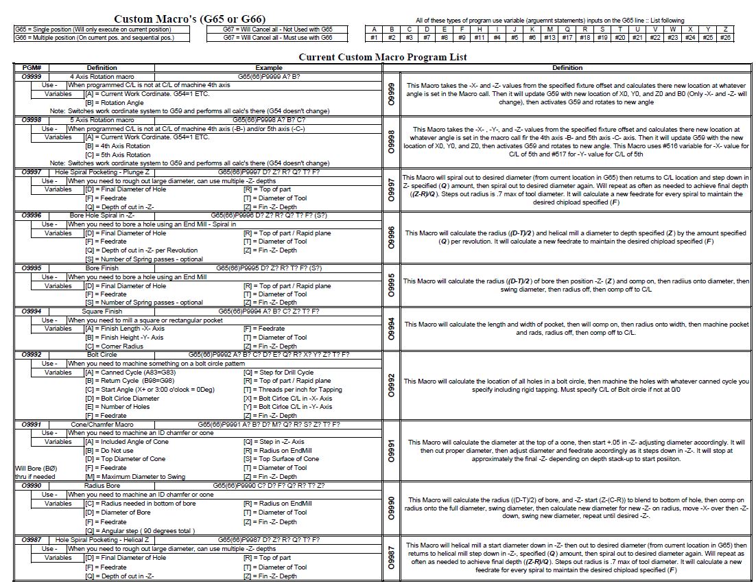
If anyone is interested, here is a cheat sheet of some of the macros we use.
-
We use custom macros for just about everything here. For example, Engraving, Helical Bore, Bore, Hole Chamfer, Thread mill, back spot face, etc. As well as common machine functions, 4th axis rotations macro, 5th axis rotation macro, home position macro
-
1
-
-
Looks like to me you need every 'C' move that was posted. As far as feed rates, are your Feed, Plunge, and retracts rates set all the same?
-
Colin,
I went back and started messing with the supplied posts that came with MasterCam and tried to use just numbers in my comments. Apparently MasterCam will not post a comment that doesn't contain a letter in it somewhere. Could this be a bug?
It does not appear to be related to our engraving macro, but an issue with how MasterCam handles comment without letters.
Maybe someone else can verify this?
In the meantime, I'll go through and try a few other supplied posts to see if I can find one that works.
Thanks

Needs some Fanuc Macro Gurus help.
in Industrial Forum
Posted
Ahaslam,
Thanks for the reply. But I don't think I explain this well enough. In your example, you have a know sphere diameter, when I'm finding the centerline of the nutting axis, I won't know the exact radius. For example, let say I have 4 points in space;
point 1 X0.|Y12.| Z3.0, point 2 X8|Y1|Z2, point 3 X-2|Y-6|Z-3 , point 4 X -11|Y2|Z4
Now given those 4 points I should be able to calculate the Center swing as X-1.5879|Y2.5125|Z1.6583 - And I only know that because of those handy, dandy calculators on the interwebz. And then I can compare that to my parameter 19700, 19701, and 19702 (X, Y, Z, Centerline) and make adjustments automatically.