


Aaron Eberhard
-
Posts
1,426 -
Joined
-
Last visited
-
Days Won
106
Content Type
Profiles
Forums
Downloads
Store
eMastercam Wiki
Blogs
Gallery
Events
Posts posted by Aaron Eberhard
-
-
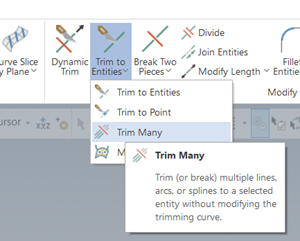
Are you talking about "Trim Many"?
-
- Popular Post
- Popular Post
Tl;dr - Cut Pattern > Style to Guide instead of Parallel, or, Advanced Options for Surface Quality > Method > Exact instead of Approximate.
----------------------------
The reason for this is the collapse of the pattern due to your tool axis control.
If you turn off collision control and set the Tool Axis Control back to "surface", here's what the "raw" Parallel toolpath looks like:
When you turn on Tool Axis Control set to Fixed Angle to Axis (good call, BTW), it keeps all of these passes, but it's now trying to keep the same surface contact point with the new tool position. Since the toolpath is set to Center/Tip, it looks worse than it would if you could see the contact point, but that's still a really fine stepover for a fillet at the bottom.
The changes I would make:
Change the pattern type to (2) Guides instead of Parallel. That'll let the toolpath blend between the top and bottom better and you can benefit from Machining Geometry > Calculation Type > Tool-Center Mode (the default), where it's smart enough to calculate it based on the tool center. It gets rid of the gouging/fishtailing you have on the corner as well. When your fillet is almost the same size as the tool like it is in this case, I'd recommend tightening up the Cut Tolerance, maybe .0001 instead of the default .001?
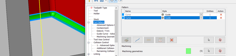
I'd also change your Collision Control to tilt to avoid the walls unless you have a specific reason to ask it to retract if it gets close to the wall? I think you'd prefer to have it tilt away. You probably don't need to use the second collision control.
-
 3
3
-
 7
7
-
43 minutes ago, crazy^millman said:
Meaning to say you have some knowledge on scanning and reverse engineering.

Taught by the best!
-
3 hours ago, #Rekd™ said:
Mine comes out clean. I linked the file.
https://www.dropbox.com/s/0kmm5gk391ft6xi/test_JF.emcam?dl=0
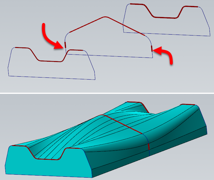
Yours shows the problem on the opposite corner.. Branch only syncs the one start point unfortunately.
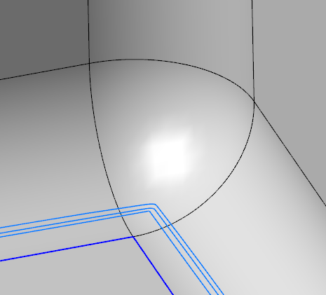
Reko - What I would recommend doing is using Sync By Entity, but to make that work, you'll need each chain to have the same number of pieces. In this case, the easy button is to leave the three pieces of the square bottom alone so they sync up nicely, and use Wireframe > Curves > Curves from Splines to stitch the rest together:
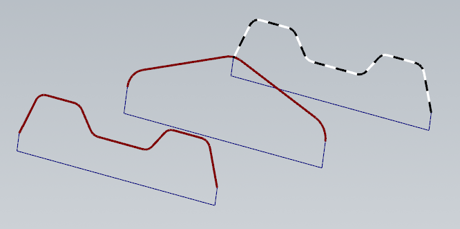
That'll keep the sharp edges on the bottom:
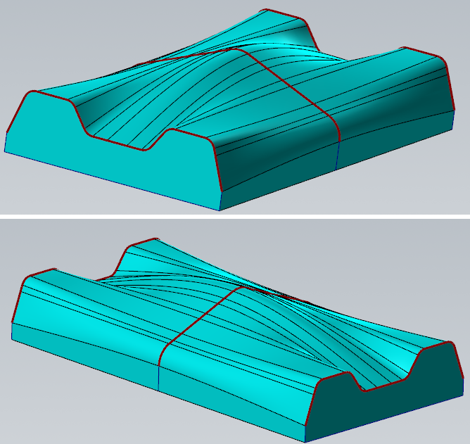
he trickier way to do it is to control the sync points if you don't like the results, but be careful, as each of the chains need to have the same sync points, something like this:
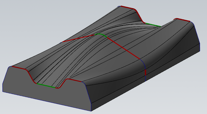
Here I wanted it to sync up the radii in the corners, and maintain that sweep, so I had to break the verticals so that the "flats" on the side had somewhere to sync up to. I think the results are better, but your mileage may vary. Obviously, you could continue this concept and manage the sync of the bulge in the middle to stretch out to the corners, something like this:
And yes, I've spent WAAAAYYYYYY too much of my life working with surface sync points!
-
1
-
6
-
-
1 hour ago, Azoth said:
Okay thanks. I haven't even gotten to the gear tool yet because right off the bat I ran into an issue with the way mastercam calculates it's facing toolpaths (it prioritizes from the center out with symmetric tool overlap off the sides of the part, but straight ignores my stepover distance which leads to an awful toolpath that leaves a mere sliver on last pass because they made it prioritize tool overhang over my specified radial tool engagement). The only solution I'm seeing is to manually offset the toolpath by drawing a separate wireframe or just draw the toolpath, which at that point why am I even using cam? Do I really have to hand edit my cam's gcode in "state-of-the-art" software if I want optimized toolpaths?
So yeah the chances of it being capable of calculating toolpaths based on constant chip area was starting to look like a long shot, thanks for confirming.
Obviously the 3d surfacing toolpaths that can't be done at the control make mastercam valuable, but I'm just shocked with how lacking mastercam is in the fundamentals.
You would likely benefit from some instruction from your reseller. Barring that, sounds like this would be a great time to post a file and ask for assistance from this awesome community
.gif ":)")
-
1
-
-
Out of the box, you're not going to get that level of intelligence. You would need a custom add on written to take that surface area of your engagement into account and create your passes that way. The same problem exists in thread milling & full engagement t-slotting, but normally it's not a enough deal so the easy solution is just to create two or three toolpaths with different rough & finish parameters, but you'd have to calculate the amount yourself. With a T/slot or thread-mill, though, the variation is generally not so large that it really matters.
Your reseller should be able to help you out, or you can reach out to Byte on here (https://theebyte.com/), or give me a shout as I have some resources that do custom add ins as well.
-
1
-
-
7 hours ago, volitan71 said:
I guess one you get it set up the way you like it... Look at that ribbon or whatever they called it back then. It's kind of a disjointed mess. Unless I'm not understanding the method to their madness, which is quite possible.
Glad you got it up and running!
Yeah, that was a common problem on the X series... The toolbar positions were saved in whatever resolution the developers used, but when you opened it on a different resolution, it would randomly space them around, and you had to slide it back.
It worked really well for "custom" interfaces, though. I had an installer for my Centroid customers that would go through and configure all of the Settings > Config things I needed, as well as give them a custom button bar with all the commands they needed for cylinder head porting.-
1
-
-
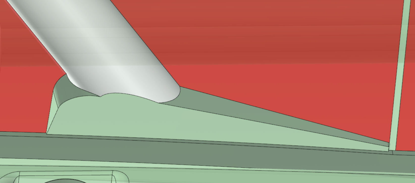
Well that was difficult! I was able to do it, but I had to undo the fillets.

If you'd like, I can create a video showing how I did it. There was a lot of iterations of Simplify/Optimize, modify feature/fillet, push pull, etc.
-
1
-
3
-
-
Looks like it's available via the Internet Archive's Wayback Machine:
You can right click on the file and choose "Save Link As" and it'll download. I don't know whether it works or not, I don't have the capability to run it
There's also a lot of sketchy looking sites that host if you google the EXE, but I trust archive.org!
-
3
-
-
I've used various ATI cards sporadically throughout the years from the general gaming lines up to the Fire (professional) lines. In general (note: blanket statement, take it for what it's worth), the hardware was quite good, sometimes even better than nVidia in the comparable generations. The thing that always caused problems was the drivers & openGL implementations. So, you might have smoother/more responsive behavior, but it'll suffer a video crash once or twice a day kinda thing.
I haven't used them in a while. I've heard it's a lot better now.
I wouldn't gamble my dollars on it, though.
-
17 minutes ago, crazy^millman said:
Yes just like i want it to. It can be minimized, but if that is the hill you are going to choose to go to battle on then your choice to pick it.
My Varco Reports opens in the whatever window size I last left it in.
-
2
-
-
46 minutes ago, gcode said:
Dang, I'm getting old!!
The Quadro 4000 is 13 years old

-
 4
4
-
-
7 minutes ago, JParis said:
and the Geforce answer bites yet another user
Yep... Another company making stupid naming decisions, too.. It used to be easy "Just make sure you get a Quadro!"
Now, it's "Make sure you get an RTX, not a Geforce RTX!" "In terms of how this affects product naming, NVIDIA GeForce GTX and NVIDIA GeForce RTX GPUs are separate product series from NVIDIA RTX GPUs." Yes, I had this link handy because I've sent it to three people in the last two weeks.
Sharles - Any idea what video card your coworker has?
-
Just to be clear/pedantic - When you say slow down, is it the simulation itself slowing down or the interface (opening menus/changing translucency, etc.?).
-
2 hours ago, Thee Rickster ™ said:
So we are hoping to automate it somehow to find a solution.
Generally customer sends a new file, it goes through our CN tracker and a CN flags the
production job, we Move the current rev data to an obsolete folder and place the new rev data
in the main folder.
i will look ing the the SVN, Vault as you stated,
Thanks a bunch
There's a chance this could work for you.. I just learned about it today (thanks again JP!), but it sounds like it might flag a warning when you open the file (if you have it turned on to check at file open). That might be enough...
-
I'm guessing this is not robust enough to solve the problem for you. It can only tell you when there's a similarly named file in the watched folders as the one you manually added to the list.
You'd still be better off with a version control system such as SVN, Vault, etc.
-
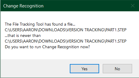
Oh, I'm trying it in 24...
If you're saving new revisions with different file names (i.e., Part1, Part1 v2, etc., etc.) you want your list to look like this: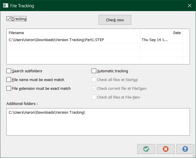
Note that I have "file name & extension must be an exact match" set to off.
Then, when I ran it, i get this:
It does not tell you if one of the .step files you used is deleted, though. It has no knowledge of that.
-
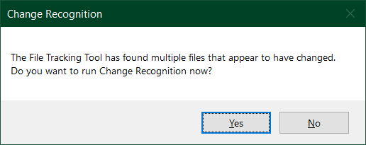
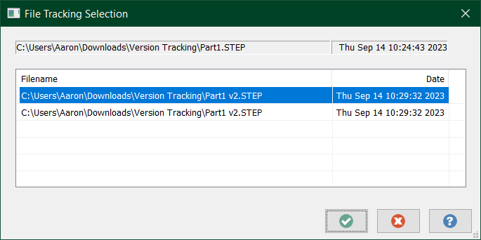
I just tried it over here, and I had to run "Check All Tracked Files":
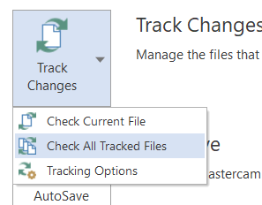
If I just "check current file" it only changed the Mastercam version of the file. Which I guess is useful if someone changes the Mastercam file while you're working on it?
-
1 hour ago, JParis said:
For a solid, Under File >> Track Changes >> Choose the options
Click Tracking in the top right
In the window, Right Click >> Add...select your file to track...
When you open the Mastercam file it should check for changes
59 minutes ago, crazy^millman said:Thank you I just learned something.
Cool! Me Too! Thanks JP!
-
1
-
-
2 hours ago, jpatry said:
It would be nice to have 2D dynamic rest paths work from a stock model, though, they would play well together with optirough that way
I completely agree. All of the toolpaths I looked after are stock aware (hole making and multiaxis)
-
1
-
-
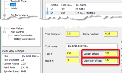
Ah, okay, that's a different problem and changing the CD wouldn't be it.
I've never had a tool change T/H/D on me unexpectedly.. I know that you can change the H or D offset # in toolpaths > Tool page without it throwing up a warning and it's only saved with that toolpath:
I've accidentally filled out the wrong field due to fat fingering when using tab to move between fields?
If you can catch in the act, I'd send a file over to QC to see if there's anything logged against it.
-
Have fun!
-
1
-
-
Can you post your model up? It might be as simple as choosing the solid face of the hole instead of trying to snap to an edge.
-
1
-
-
As Ron Said, it's probably this:

I have that set up on my Robodrill for example, where it's old enough that it doesn't understand a diameter offset for tool #5. I have to use offset #5 for the length, so I have the Diameter offset set to 100 so it will give me 105.
Also, make sure that nothing changed about using head numbers.
-
2
-
Trim Filter
in Industrial Forum
Posted
Ah, I think you're talking about Edge Selection: