xycnc
-
Posts
57 -
Joined
-
Last visited
Content Type
Profiles
Forums
Downloads
Store
eMastercam Wiki
Blogs
Gallery
Events
Everything posted by xycnc
-
Modular "screw-on" milling heads/shanks
xycnc replied to MIL-TFP-41's topic in Machining, Tools, Cutting & Probing
Check out Ingersoll chip surfer series. Its a T15 head. only have 1 insertable head option but could also by solid carbide bits. Part number S125T15CK-80, Total shank length is 12inchs. Insertable head part number is1SJ1Y-10012TURO1. Hope that helps. -
I am In the process of trying to convince management into buying space claim. Mainly for the fact that we get so many bad solids in from the customer. Can some of you give me some good pros to add to my list. Also liked the ease of making fixtures and the like. Thanks
-
I am not sure if I understand what you are trying to do, but why don't or aren't you using dynamic core with step ups? And on your 2d dynamic you need two chains. One you stock shape and the other you basic part shape. That's if I am seeing what you are trying to do correctly.
-
Dynamic Milling with open pocket
xycnc replied to Justin Beebe at Folsom Tool's topic in Industrial Forum
Crazy thanks for the input I will give it a shot. You made some great points. I just hope my toolholder can hang on! -
Dynamic Milling with open pocket
xycnc replied to Justin Beebe at Folsom Tool's topic in Industrial Forum
Nice work guys love the videos. I struggle trying to figure out If I want to take a bigger step over or a smaller with more feed. Never really figured out what works "faster" We have a local tool grind shop around here that makes so really good endmills. Place is called Oakview Tool and they supply a lot of the Medical shops. I will try to post a few videos myself. But I've have a 3/4 rougher (5 flute) with 2.25 loc that is can take full cut at 20% (.15) stepover 600sfm (3056 rpm) at .01-.015 per rev (33ipm) and it loves it. I was told I could run anywhere from 500-1000sfm all day any day with these cutters and the guy hasn't been wrong yet. -
Dynamic Milling with open pocket
xycnc replied to Justin Beebe at Folsom Tool's topic in Industrial Forum
No problem. Just glad I could actually contribute for a change. -
Dynamic Milling with open pocket
xycnc replied to Justin Beebe at Folsom Tool's topic in Industrial Forum
check this out it shows many other ways to chain other shapes too. -
Dynamic Milling with open pocket
xycnc replied to Justin Beebe at Folsom Tool's topic in Industrial Forum
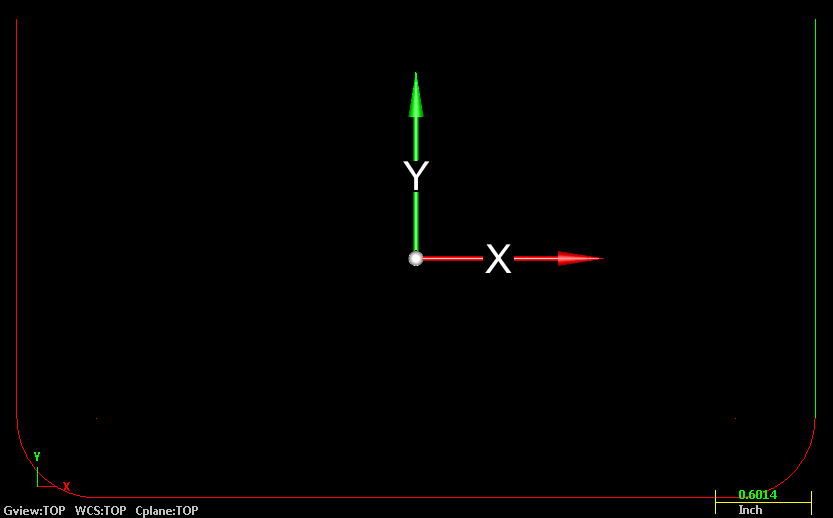
You can add an approach and end results should look something like this
-
Dynamic Milling with open pocket
xycnc replied to Justin Beebe at Folsom Tool's topic in Industrial Forum
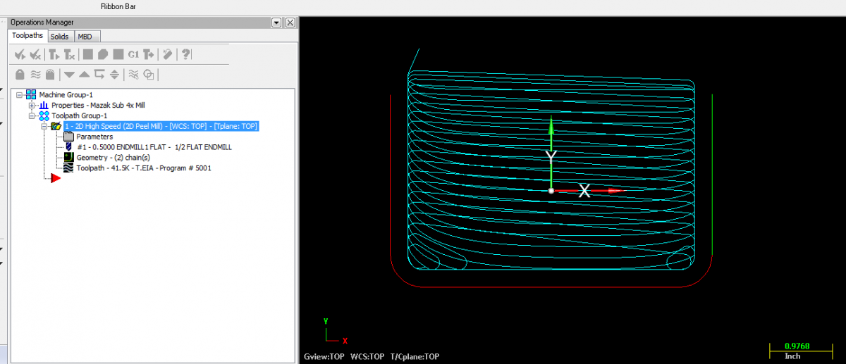
Give this a try... I think this is new to X7 but I use it all the time first chain is the red lines and second is the green, Using peel mill.
-
thank you for your help. I got the part done and they were pleased.
-
Ok after messing around a little more I think I kinda figured out what you did. You picked the outside of the slot and then unrolled that geometry. Then you offset that geometry by half to give you a centerline. Then rolled that around to .875 to get your geometry in center. Then used the c-hook roll die. Am I close?
-
JParis this looks like what I wanted. Now If you could help me by explaining how you got there? I found rolldie under Chooks but just how you went about creating Geometry. Thank you for your help I really appreciate it. Also am I correct in that I will have to take the toolpath you gave me and then just using 4 axis sub is X? Thanks again so much Cory
-
Ok new question... I just talked the designer and he said that inventor doesn't draw the cam model correctly. Can anyone maybe help me out to try and get it drawn right? Part rotates 90 degs over a 2 in spread. maybe Im fighting a lost cause here but looking for any help. Maybe I should just try it in Mazatol instead, but I'm trying to learn something also Thanks again Cory
-
Thanks greg for your quick response what create curve should I use to get it in the center of radius?
-
HELP!!! I am new to programing on 4th axis programing and I need to do this Job. Any help or ideas would be great I really think its not a hard job, I just need pointed in right direction. It is going to be done on a Mazak with a rotary in the X axis. It is the cam action that I am needing help with. Thank you I hope file uploads 47670-004.MCX-6
-
Is it possable to edit your post to make this an option on or off? Or is it something that you hand edit in? Or it does it all the time?
-
Just wanted to post an update. I changed the post to I,J,K and part looks great! Thats what it was. Thanks everyone for you time.
-
Alright I guess it sounds like I should change it from R's to IJK's. I will rerun it in a few days and see what it does. Thanks again for input everyone.
-
Thanks everyone for your help. G code No i haven't changed post to I,J,K was wondering if it would make a differance before I tried, Joe: No Im not running G61.1 but i have thought about doing that. Jack: The feedrate was 85ipm for finish pass and 185 for rough pass. What picture didn't show was that it too giged the part (rough pass). Jammin I haven't ran this part twice. I had it do it to me on a plastic mold a while back and it did do it kinda in the same place but the second time it did it, it was worse. Im really thinking its the the posting out in R's. Because it seems to do it on Round shapes. I ran a plate to inspect the machine where I cut a circle square and triangle and bored for holes to check it out and everything came back good. But those were all 2d paths. Thanks agian.
-
I have tried slower speeds. I'm not sure how slow I need to go if thats the case. It seems to do it on round shapes. On one part a 3/16 ball at 35 ipm and it still did it. This job was Al and I ran a 5/16 ball at 85 ipm. Thanks for the response.
-
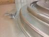
Here is a picture of the part I hope you can see what im talking about
-
I have a Mazak vtc-300c and am having some issues with the part having major undercuts or gouges from the tool path. I thought it was the machine at first but we looked it over and can't find any backlash issues with it. So we are trying to figure out if it could be a post issue. I was wondering if it could be the fact that when in post out circle it post out as R instead of I and J's. Does anyone out there know if this could cause something like that. I will try to put up some pictures of the part later. It verifys ok on mastercam. But it acts like it looses where its at and at time will gouge in for like a half circle and then be fine in random area's. I was using high speed tool paths Opti core and Hybrid. I dont think its over travel. It seems to do it on Round shapes that is why I was thinking it was maybe a post issue. Any input is greatly appreciated. Thanks in advance.
-
No there is no rotary it is really just a simple 2d path. Sorry it took so long to respond I work nights Thanks again I hope this helps a little. Its just the outside profile. cam1.bmp
-
Well right now I am just trying to rough the part out so im not to concerned with finish. But thought i would at least have the chance to see what I could get before it is the finish pass. I am going to be using just a 2d finish pass I think. I have been playing around a little bit trying to turn it to arcs. I think i got that. I guess another question is if i play with my filters to much how much will it affect my toolpath from the origanal? will see if i can atleast post some of the file. thanks agian for your help. It doesnt help that the part is bigger than machine table. but Im sure we have all been there.
-
I search this topic and The latest i could find was from X4. Was hoping maybe X6 would be better. I have a part that is a cam and its geometry is a spline. Part calls out for a very smooth finish. Was wondering what i have to do to make it smooth. I was thinking that there was a convert splines to arcs. But didn't know one if that would do it or two if i was wrong. Part is S7 and appox 30 X 32. Any pointers would be greatly apprciated. Thanks in advance.