


NOTW Programmer
-
Posts
469 -
Joined
-
Last visited
Content Type
Profiles
Forums
Downloads
Store
eMastercam Wiki
Blogs
Gallery
Events
Posts posted by NOTW Programmer
-
-
We have a Mazak Variaxis I800, the guys at the floor only have the option to use Restart 2; this is non-modal. I emailed Mazak and they said that Modal Restart cannot, i.e. Restart 1, cannot be used due to the explanation below. Anyone have any say on this, seems like the machine would be able to pick up and read all the previous codes no problem. The Mazak Manual even offers the option and does not warn about any complications.
G54.2 - Dynamic Offsetting II
Restarting in the program cannot be executed inside of G54.2 mode.

G54.4 - Work Position Error Comp.
Restarting operation from a block in the mode of workpiece setup error correction begins with a movement to the accordingly corrected position and to the position without correction, respectively, in the case of using the [RESTART] and the [RESTART 2 NONMODAL] menu function.

G05P2 G61.1 - High Speed Smoothing
Alarm is generated.

G43.4 - Tool Tip Point Control
Alarm is generated if restarting is done inside of G43.4 or on the line of cancelation, G49.
-
Have you gone through the Active Reports Training Tutorial? If you have not I suggest you do, if you don't have it send me a PM.
-Bill
-
From a new / blank MC file...
Settings >> Machine Definition Mgr >> Open >> [The mach you want to change]
Open the control definition & on the Files page check / change the options under the "Post Processing Dialog" button
HTH
Even if "Ask" bubble is checked in Settings, doesn't the control definition setting take precedence ?
-
Be blessed my brother, same here, no hard feelings. You too have a great weekend !
-
Bill where were you when this was originally posted?............................................. I love helping others and sharing my knowledge to help others. I do not have all the answers and learn as much and they hopefully do sometimes helping others with a problem. Want to help him make it cut better, great we are all ears and waiting to see what that answer is.
Lackluster sure, my point was performance not demeaning at all. Anyhow I didnt even notice the date on this thread, I was looking for an answer on a different subject myself and my search word brought this thread up, gotta refine that....lol JK ! Im guessing that Dragracer1951 is content with his results since he didnt ask for anything else.
Bill
-
Merely making a suggestion, Yes my comment could have been worded better, interesting enough the comment wasn't directed to John but the original thread owner. He hasn't replied why is everyone else taking offense to an observation that could help bring something up that might have gone unnoticed otherwise.
Bill
-
Not picking apart, wow you get offended quickly. Anyhow if you ran verify you would know what I mean, I only meant it as a suggestion as the program cuts tons of air. Merely making a suggestion ! But hey, not my part or my shop.
Bill
-
That was easy ! Why is there so much air cutting ? Did this really take an hour to cut ? I'm sure we can find better ways to cut this, no offense !
Bill
-
I have a lathe post that works very well for our Okuma Lathe, but it is only with V8, we have X5 and would like to be able to use the same post processor, i thought using the C-Hook update Post would work but it doesn't seem to be doing that...Any help would be great!
Is there any specific formatting you would like to keep that you cannot use one of the new basic posts. I have X5 installed still I can help you there or if you want I can modify the post to your liking. Send me a PM so we can discuss this via phone !
-Grey
-
I have been trying to make tool assemblies in the Mastercam Tool Manager and I can creat the assembly, drag and drop the holder to the assembly, but when I try to drag and drop the tool to the assembly it will not work. It just displays the circle with the line through it and will not attach to the assembly. Anyone have this problem?
I had It when X7 came out, haven't tried it since !
-
Check you locale settings in control panel. Might still be set to Korean !
-
I had the same problem with coolant M code location. I wanted it on the G43 Z* H line, regardless of wether it was set to before, with or after.
I can dig out the info for you if you want. It means that Canned Text won't work properly, but I don't use that anyway.
Sure why not. I can use all the help I can get. Did you get the coolant to turn off with the retract move as well ?
-
I hava DeVlig Horizontal Boring Mill, B rotary table and C rotary table. I have gotten it to work properly with the following settings:

-
This is how I do it:
Program all ops that need transformed normally.
Transform Toolpath with the settings shown in pics. (set number of instances you need)
Then just assign multiple offsets at whatever locations you need on the machine.
it will run each tool thru all offsets before repeating with the next tool.
Is this what your looking for Bob??
I have done this with a max of 4 tools and axis substitution with incremental subprograms. If I remember correctly having the group NCI output option set to operation type, will run the first tool in its entirety before making a tool change. You must have also programmed the T1 and not called it back in a later operation if you only want to see it once. You still have to create separate work offset at the machine for each instance of the features or you can always use G10 and shift the G54 offset for each instance.
-Bill
-
Here are my settings in both the spindle alignment and machine matrix. Looks the same per Crazy's comment.
#Table/Table spindle axis alignment. (Typically Z+. Always Z+ with nutating machine types!)
# Choose the axis that is parallel to the spindle with all rotaries at their zero positions.
spind_align : 3 #1=(X+), 2=(Y+), 3=(Z+), -1=(X-), -2=(Y-), -3=(Z-)
#Machine base matrix (Base matrix to map positions into)
matb1$	 : 1
matb2$	 : 0
matb3$	 : 0
matb4$	 : 0
matb5$	 : 1
matb6$	 : 0
matb7$	 : 0
matb8$	 : 0
matb9$	 : 1
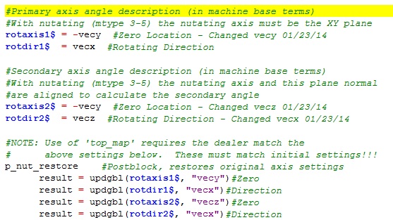
I got a hold of the 5ax Post Guide and was able to define my rotary properly. It turns out that my brain was thinking B rotaxis1$ was Z+ when in fact rotaxis holds the location for B0 not where B rotates about.
#Primary axis angle description (in machine base terms)
#With nutating (mtype 3-5) the nutating axis must be the XY plane
rotaxis1$ = -vecy #Zero Location - Changed vecy 01/23/14
rotdir1$ = -vecx #Rotating Direction - Changed vecx 01/23/14
#Secondary axis angle description (in machine base terms)
#With nutating (mtype 3-5) the nutating axis and this plane normal
#are aligned to calculate the secondary angle
rotaxis2$ = -vecy #Zero Location - Changed vecz 01/23/14
rotdir2$ = -vecz #Rotating Direction - Changed vecx 01/23/14
By the way the default way the POST is setup is for a trunion with the rotary pointing left. Like the HAAS TR110. I read on the guide that the matrix is to be changed if you want a different orientation than the WCS uses, the guide does not provide much detail about these settings.
Colin, now that I have your attention I was trying to modify a lathe post based on the 2x generic slant bed. I want the group name as the program name and the coolant M9 to be posted with the retract move. Is this possible? I have another thread started http://www.emasterca...topic=76228&hl=
Thanks for your help,
Regards,
Bill
-
It sounds like you've got a Horizontal machine if you want Top WCS/Front Tplane to be B/C zero. You will need to change the Machine Base Matrix in the post to accomplish this. I would recommend contacting your Reseller for a copy of the 5 Axis Post Guide. This is a PDF file that explains how to setup the Generic Fanuc 5X Mill Post.
I tried that already, it took them weeks to decide to want to sell me the X7 Post Ref Guide for $50. I'm talking about over a month and after repeat messages about it !
Is there a better approach to achieving what I want, perhaps starting with an MPMaster HMC Post ?
-Bill
-
Hello,
I am attempting to make my own 5 axis post off of a Generic Fanuc 5X Mill. I have a problem with the B and C rotations, they are backwards; the coordinate shown by B should be C's and C's should be B's. My TPlane is currently the FRONT and my WCS the TOP, I should be getting B0. C0. at the time. I tried changing the machine definition but apparently that doesn't work. The C axis Rotary table is looking to the X- direction and A0 would be the same as B0; the FRONT plane right ?
T1 M6
M8
G0 G54 G90 X3.0163 Y9.8092 C180. B-90. S534 M3 -------> Should be B0. C0.
G43 H1 Z5.
Z3.1
G1 Z3.05 F8.56
I tried changing the rotaxis1$/rotdir1$, rotaxis2$/rotdir2$ but I keep getting the wrong rotation or when rotation seems fine I get the spind_align error when posting.
-Bill
-
I like the FSWizard, nice interface. I really like the GWizard by Bob Warfield, Its a complete calculator. I just came into using the FSWizard; its missing a few things like tapping and when turning the GWizard mini-calc does a little more.
-Bill
-
You are right on the dot about the period; it does consider it an extension after that. That also explains why I cannot have the / since windows considers it a path separator. I was able to post the heading I want, however I must save the NC file as that complete heading then change it to what I want the file to be named. Is there a way to use the group name as it is posted. Also any word on getting the M9 placed with the retract move ?
-Bill
-
There must be a character limit, I manually enter the information but it stops at a certain point and you cannot use / in it. This is what we want, this is for our lathe lead.
CUSTOMER P/N 2133252-101 REV. NC OP#1
-Bill
-
Sorry guys, forgot those details. I am using a Lathe 2-axis Slant Bed as a starting point, I take it IHS not MPMaster. JPrais, I was using X style coolant but when I switched it to V9 the M8 appears right where I want it. How do I go about the program name to be the group name ?
- Bill
-
Can you guys please help with these simple MODs, I can pin down the solution yet !
O1392(1392) ------------------------------------> I want the group name here.
(CHUCKING DEPTH)
(CHUC PRESSURE)
(CYCLE TIME)
G20
N100(OD ROUGH RIGHT - 80 DEG. )
( FC RGH )
G0 T0101
M8
G97 S1000 M03
G0 G54 X1.7 Z.03 ------------------------------> Want M8 here by default
G50 S1000
G96 S500 M03
G72 W.1 R.01
G72 P1 Q3 U0. W.005 F.01
N1 G0 Z0. S500
G1 X0.
N3 Z.03
G0 X1.7 -------------------------------------------> Want M9 Here by default
M9
G28 U0. W0.
M01
(*)
-
This is because you are using an non standard WCS in your stock setup - try changing your stock setup WCS plane to TOP and it works fine. This is a bug that I have reported to QC.
Funny thing is that I use non-standard all the time and 90% of the time it works all the time !
-
Sometimes my edge breaks look like they're done with a chisel .
Same here, what's up with changing resolution and having to restart the simulation !
Tool Parameters Screen Clipping
in Industrial Forum
Posted
My colleague got his new Laptop and the attached image is what he gets when opening the Tool Parameters page. He had to set his DPI to 110% in order for this to clear up. I think this might be a driver problem as his images are also jagged. Anyone experience this? I didnt find anything when I searched the forums.
-Grey