


MrFish
-
Posts
532 -
Joined
-
Last visited
-
Days Won
1
Content Type
Profiles
Forums
Downloads
Store
eMastercam Wiki
Blogs
Gallery
Events
Posts posted by MrFish
-
-
its here, but there is a bug with it not retaining its setting, as in if you un -check it, it doesn't retain that setting and rechecks itself. Is logged.

-
Fixed a "sliver" issue for me in one of my dynamic tool paths, but i wish they would make it recognize the chamfer/corner rad on the cutter when facing so as not to leave the little stand up at the end of a dynamic facing tool path.
-
Personally I would stick with 2023 as the bugs have "mostly" been ironed out and for me the lack of thought for stock/fixture management when programming second operations in the same machine group is a real no go at this stage.
-
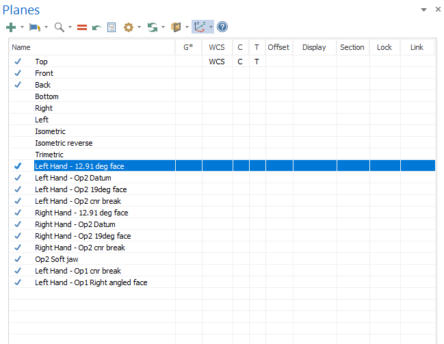
Anyone know if there is a way to reorder the custom planes in the plane manager. Don't want to reorder the factory planes but my machinists OCD would like to be able to have my Ops planes in order ?
-
7 hours ago, Jobnt said:
So it just lasts for that one session of simulator?
Thanks!
Yes, no way to save them as far as I know.
-
 1
1
-
-
I believe they are more for a reference to jump back too. Once you create one you can click on it and simulation will jump back to that point. Handy if you have auto create on and no stop at collision. Then you can run simulation right through and only jump back to reported collisions if there are any.
-
1
-
 1
1
-
-
50 minutes ago, gcode said:
I use a separate Machine Group for each operation.
Been doing it this way for years
I don't do this as i want an update to a tool to be reflected across all the operation groups, but this is the beauty of machining, many different ways to get the same out come with each having their own style.
-
2
-
-
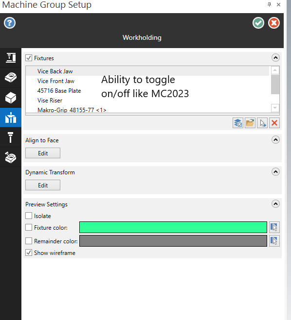
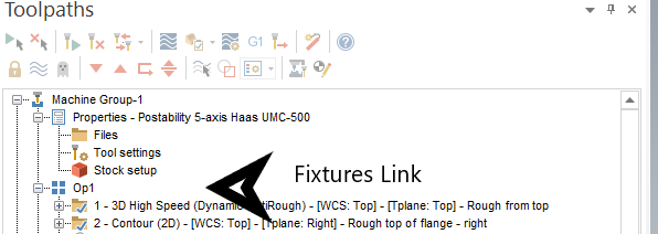
As I begin to use 2024 in my day to day programming the biggest annoyance for me so far is the selecting of fixtures. My work flow with mostly 5 axis programming is to setup the machine group setup, including stock and fixtures, then program Op1, verify/simulate, create a stock model and program Op2, often requiring soft jaws/different fixturing, I then use the stock model as stock to verify/simulate Op2. In MC2023 I would then use the Simulator options in the Toolpaths manager to toggle the Op1/Op2 fixtures off/on and verify/simulate Op2. Now with MC2024 I have to go back into the machine group setup and delete my Op1 fixtures and select Op2 fixtures. Then as i like to save my file with Op1 active I have to go back in again and delete Op2 fixtures and reselect Op1 fixtures !, this is time consuming and frustrating !!
CNC software, could we please get the ability to 1, enter the fixtures tab directly , maybe below the stock setup icon in the machine group ?, 2. Be able to toggle on/off the fixtures we want active without having to delete/reselect them each time ?
-
1
-
 1
1
-
-
On 6/9/2023 at 5:41 AM, crazy^millman said:
Tools was already there just not in the layout it is now. What drives me crazy is no where for holders. Why do we ave two separate database for tools and holder? I put everything in one and use it. A lot of our customers have headed in that direction also, yet the process is still not following customers uses for doing the programming process. The whole machine group layout clearly shows that is also the case. Make it how someone thinks it should be and not what is best for customers. Or we are really the fringe of users and the majority only every program one part at a time and what we do it so extreme we will either have to adapt or stick with a version that supports the way we do it.
This software seems to be getting aligned to "new" users more with each version, often losing some of the functionality that the long term power users like/need.
-
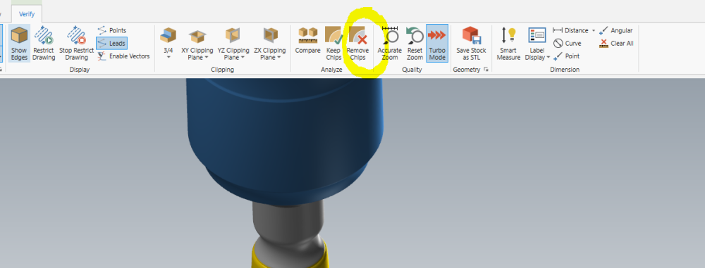
yes, use the remove chips button, click on it then click the chips and they will be deleted.
-
1
-
1
-
-
On 5/24/2023 at 12:44 AM, AHarrison1 said:
Toolpath is not displayed
That's it, was another programmer who had inadvertently clicked the toggle display button and as we don't have tool paths displayed all the time it wasn't obvious as to what it was. Thanks
-
3
-
-
Anyone know what the opaque folder on Op8 means, don't think i've ever seen that before ?

-
4 hours ago, JoshC said:
hmm im not sure but i did see this setting 156 info here https://www.haascnc.com/service/codes-settings.type=setting.machine=mill.value=S156.html, could that be the problem maybe settings 156 related?
- some more info on that setting that i stumbled across https://www.haas.co.uk/resources/better-techniques/control-tips/developing-offsets/
Thanks Josh, this G156 only outputs the tool Length and dia offsets, we like to use the other output as it saves all the tool page info, including tool names, types etc. This is where the savings in time can be found not having to re-enter all that data each time.
-
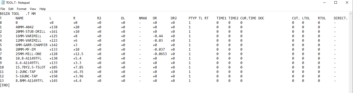
I don't have access to a 530 control anymore but used to load partial tool files all the time, not from inside a G code program though.
You can export your tool.T file and delete the tools you don't require, then re-import it from the tool file page. Think from memory you might have to use the copy soft key and when you do it prompts you if you want to over write the tools, as you only have the tools you want it only changes those ones and leaves the others as be. Sorry working from memory without a control in front of me, but hopefully this helps.

-
1
-
-
Does anyone know if its possible and how to modify the "offsets" file that you output from the "list Program" "F4" file on a HAAS NGC control.
I want to be able to truncate the file to include just the first 30 or so tools. Maybe a few work offsets. If I do modify the file, the control warns me on loading and asks if I want to load it but doesn't change anything. I'm assuming because of a format error.
I've been told by HAAS that you can't do it but from memory I did it at my last place of employment, just can't remember how !!
see attached
-
Haven't got a lot of time to play, but if you turn on some collision control you will stop the cutter trying to cut through the surfaces.
Also looks like a crappy surface to program from !!
-
1
-
-
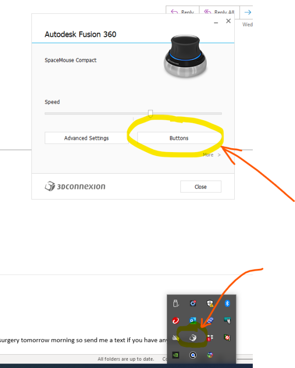
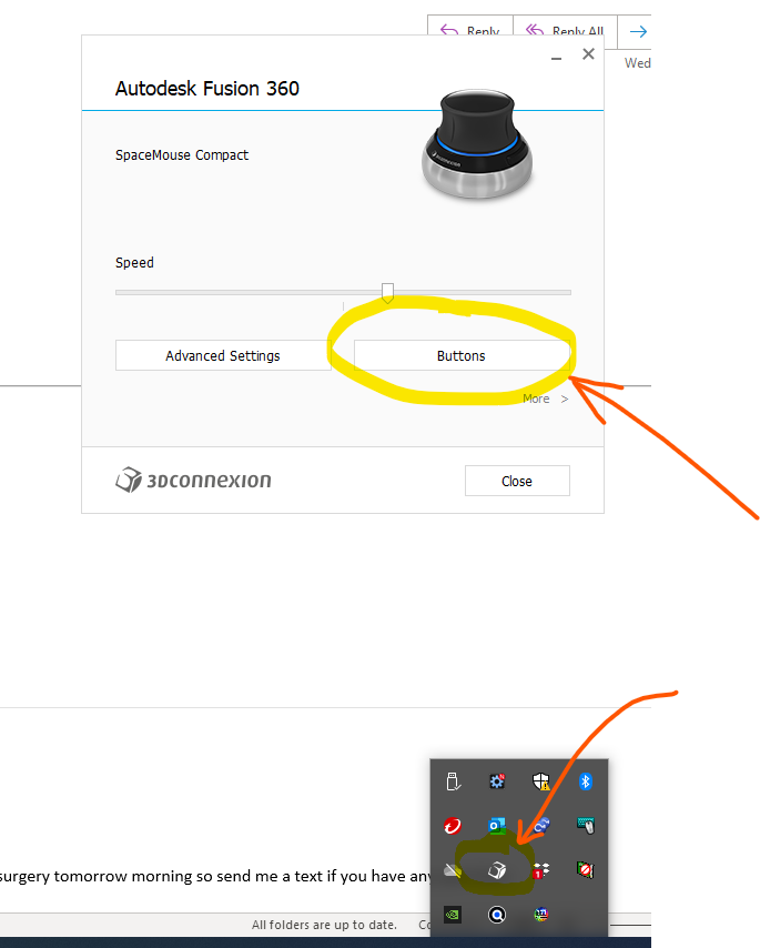
Expand the hidden icons in your task bar and then open the 3Dconnection main console, then use "buttons" button to customize them. Just make sure you are using the spacemouse in the program you want to customize for.
-
1 hour ago, TERRYH said:
Here is something new I have never seen before, when we do our trim dies we cut the trim steels and punches leaving .02 on the trim edges, then the die is assembled and we put the whole assembly back in the machine and do what we call a hard cut (remove the .02 stock on the trim edges) this had 6 different tools total, and a total of 26 programs because we have them run all programs and give finish points for them to check to verify stock and then we give them programs to use as "spring cuts" with larger step downs so they run faster and they can us new tooling if the others were dull or chipped. in 2023 all program names match my instruction sheets and all tools match corresponding programs, all programs were posted at same time 1 thru 18 were fine BUT 19 thru 26 all had the wrong tool numbers and wrong tools for the corresponding programs not sure how that even happens. the operators seen it when they started the programs watching the header info in single block so luckily nothing but time was lost. I re-opened the part double checked my stuff did nothing but re posted them with zero changes in MC and they were all correct. stuff like this drives me crazy because we don't know why it happened, and just continues to add to the list of things we have to watch and worry about.
Is this in MC2023, we had something similar where an operation was effectively dirty, but didn't show as so and posted incorrectly. A regeneration of the toolpath fixed said error.
Also while we are all having a rant, why does a transform toolpath operation still post out a ghosted operation from the source operations. How if that operation is ghosted and the transform operation looks to its NCI does it even get posted out, this is in MC2022 and 2023
-
On 1/20/2023 at 11:22 AM, billb said:
When flowline was first released, it only handled a single surface. Then was added the ability to handle multiple drive surfaces by flowing along a row of surfaces (crossing over one shared edge between two consecutive surfaces). Later, was added the ability to handle a wider set of connected drive surfaces such as multiple rows or a grid or a quilt.
The "single row only" allows you to revert back to the first algorithm, should that do a better job (on a single row) than the latest quilt or grid approach.
The top toolpath is a single row (using the single row option). The bottom toolpath is a grid or quilt with "single row" unchecked.
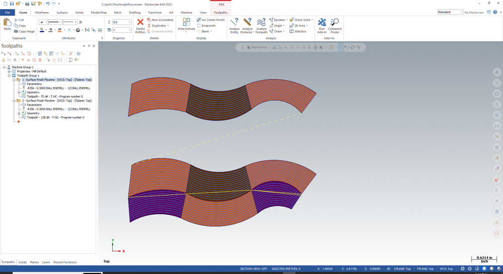
Great explanation.
-
1
-
-
On 12/16/2022 at 12:26 PM, crazy^millman said:
Change to a bull endmill with the correct radius to define it.
yes that is what i did in the example file
-
On 12/17/2022 at 10:05 PM, Joey5axis said:
Hello guys,
I have tried fiddling with these settings.
Tried machining a 190mm "Bowl" with unified multiaxis, strategy is great, single toolpath and cutting off center with a sphere mill.
However I still get the "flat spots" on the surface finish.
These parts need to be polished to high gloss so its important to me to get the best results possible.
Mind you my settings are METRIC.
Cut Tolerance 0.02
Maximum distance 0.5
Maximum angle step 0.5
Unfortunately I am not allowed to share 3D files with anyone.
Machine is a DMG DMU75 Monoblock with Heidenhain TNC640
Feeding it 10,40 or even 100MB of code is no problem for it.
I create surfaces from solid to machine the part.
Am I right thinking there is some kind of tolerance on creating the surfaces?
Thanks for the video, that was of great help especially the vector lines, that will help in the future for sure.
you could try this, Lisa from CNC software sent me it a while back
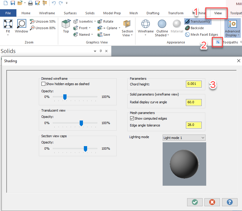
You can improve the surface (and sheet solid as well) by adjusting the Chord Height Parameter in the Shading Settings. This change will immediately render in the sheet solid, but you will need to use Regenerate display list to update the surface. Regenerate display list is not currently in the ribbon or context menu, so I customized my context menu and added it from the Commands not in the Ribbon list. Then I navigated to the view tab, and launched shading settings from the Appearance group and tightened the Chord Height tolerance to .001. Next I right clicked in the graphics view and selected Regenerate display list. Those steps removed the facets from both my surfaces and sheet solids. Let me know if this does not work for you!
-
If you have a multi axis license the unified tool paths give good "stock" control. I did have to change the tool geometry as a high feed cutter geometry wasn't allowed.
-
On 11/17/2022 at 4:32 AM, Shiva.aero said:
My company owns both Esprit CAM and Mastercam. We are in the process of procuring NTX 2000. My management has given me option to purchase 'Millturn module & post' for either Esprit CAM Or Mastercam.
I am a Esprit Cam user for last 4 years and Mastercam user for last 1 year. Still I prefer Mastercam over Esprit. But after going through this thread, I really worry that my choice might be wrong.
If post is the only problem, then I can go for Postability Or In-house solution Post. Any suggestion will be much helpful.
Thank you.
I believe if you are buying a mill turn like the NTX you will also probably want the Mill-Turn module if you go with mastercam and that is more money and I believe comes with a "machine environment" that includes linked simulation. Either way as mentioned you will need to talk to your reseller.
-
Try the axis control page - set rotation type to 3 axis, about Z, this is post dependent but will give some XY and C axis motion that may keep the path within the travel limits.


Hybrid toolpath
in Industrial Forum
Posted
I have recently had a part that I programmed in MC2023 using a hybrid tool path and it would not produce the varied step over between steep and shallow. Opened same part in MC2024 and refreshed the operation and came out perfect !!