


MrFish
-
Posts
533 -
Joined
-
Last visited
-
Days Won
1
Content Type
Profiles
Forums
Downloads
Store
eMastercam Wiki
Blogs
Gallery
Events
Posts posted by MrFish
-
-
I believe it is this box, uncheck it.
-
I posted up some code that worked on the exact same controller we have in our shop, and I queried what post the op was using, but never got a response.
Mike your post further up is just a . ?
-
I think part of the key is getting a laser cal and ballbar. We had PQI do that and holding tenths on interpolated features isn't that hard. We're scheduled to have it done once a year. According to my digital mic I'm holding .00005" on a periphery in 17-4 H900, ten parts in a row so far.
Another part is programming for the machine, with faster but lighter passes, and skim passes for finish.
Yip you've hit the nail on the head Matthew. We can hold similar tolerances in the land of metric but I didn't want to state that here in fear of the ear bashing we are going to receive from all the haters !!
-
Haas are good value for the money you spend. It really comes down to the volumetric tolerances you need to hold. +-.0005?, sure you can get close to that with good quality holders and a solid setup. I consider that most Haas machines are really a ".001" accuracy machine. If that's all the tolerance you need to hold, then they are good machines. If you need ".0001" accuracy, then a Haas won't get you there. Yes, you could get a boring head and hold a tight diameter and cylindrical tolerance on a single hole, but what if you needed to hold a pattern of holes to .0001 True position tolerance, then rotate the block and have other holes intersect the first pattern, while holding position, form, and perpendicularity? Within .001? Sure. Within .0001? Nope.
I totally agree when you are talking multi axis work with rotaries that emphasise positional inaccuracies . But for 3 axis work we can hold 0.01MM (0.0005") all day long on high accuracy medical instruments and implants. It takes a temperature controlled environment , solid and accurate tool and work holding and quality programmers that know the machines but is very achievable.
my 2 cents !
-
 1
1
-
-
Last time I worked with a DMU it was not mecanically & termically stable for precision 3+2 work... They could not reliably hold a true position of 0.0005" no matter what we did... If we wanted to hold such tolerance we had to run their 3D calibration routines before each part and run a part immediately after that...
Yip, and we are in a temperature controlled workshop and still need to do this on critical components. Apparently the new machines are a lot better though. Ours only has a temperature probe on the spindle head where as the new version has 7 of them around the machine !
I'd still go Japanese , Okuma, Matsuura, if it was my money.
-
I use this all the time, can you upload a file?
sorry no more than the stock picture in original post.
-
In toolpath parameters you can can control start of cut (left, upper left,...) that should do what you re looking for. I don't really like that but you can try mirror tranform too.
For your interest David, I had tried these controls and they did nothing at all to change the cut flow. I have seen this before and I think unless the chaining used is very simple the processing seems to just ignore this or maybe override it .
-
2
-
-
Which version of Mastercam? With the release of X8 or X9, they added some great new options for the 2D High Speed Dynamic Tool Paths.
The option I'm thinking of is "Air Chaining". You basically select a single closed chain as the "area" you want to machine out. Set the option to "outside" in the chaining selection dialog for the toolpath, and then use the "air chain" to select a "partial" chain. This tells the algorithm that the "air chain" is an "open area".
By having the path set to "outside" approach, and telling the operation "where the open end is", the toolpath should always start on the "air" side, and work its way into the pocket. I've had great results just by using those options, and sometimes modifying the wireframe geometry to keep the tool from "wrapping" around an edge where I don't want it to go...
Say for example, you have a chain that looks like the following. You want to pocket out the material, but only the "red" area is the "Air" chain area. If you just chain it "as is", sometimes it will "wrap" up past the "non Air" edges while machining its way in.
_________
| |
| |
| |
| |
|________|
Now, if you modify the chains a little bit, to extend the "walls" past the "air chain", it will only enter where the red partial chain is. Obviously this is very crude ASCII art, but I'm just using it to demonstrate the thought process here...
____________
|___ |
| |
| |
__| |
|___________|
Hi Colin
Thanks for waking me up. I new about air chain but had not thought to try it. This worked a treat and actually produced a better toolpath than I had on the good side ;-)
This forum is one reason Mastercam is so powerful !
-
3
-
-
Does anyone have any tricks to control which way the cut flows from , i.e. left to right, right to left
I have a part that is symmetrical and has an open end transitioning to a slot. When cutting from the front I get flow from the open end to the slot end which produces good swarf management , but when I cut the same geo from the back I get flow from the slot end to the open end and this leaves a nasty island that wants to get sucked into the cutter and break it !
-
Our 5 axis post needed updating by the post writer with the X9 to 2017 change.
-
Not sure why but if you just turn on axis sub with a normal op using standard geo we don't get any axis sub at posting. But if I do it this way we do. May be a post configuration thing .
scrap that, just tested again with latest post and worked fine on original op with axis sub
-
1
-
-
Maybe I'm missing something, but why don't you just draw the geometry? What does the saved backplot geometry give you? I think the op is just wanting a ramp on bore, with Z/C rather than XYZ?
Not sure why but if you just turn on axis sub with a normal op using standard geo we don't get any axis sub at posting. But if I do it this way we do. May be a post configuration thing .
-
We get this to work by creating a dummy operation and saving the back plotted tool path and then using this as the drive geometry for the operation with axis sub turned on and set to 3 axis. Works great in our DMG with C axis table.
PM me your email address and I'll send you an example if you need.
-
Garr make some good ones and they are cheap too.
-
Ah, only affecting Vericut Single Platform I guess?
???? don't know wasn't mentioned whether it was unique to single platform.
-
What is the issue with your Toolchange subroutine?
Basically get an error where Vericut can't find the inbuilt tool change subroutines in the control files. Work around is to reselect the control files for each operation every time you open the file.
-
One issue we are having with loading of the tool change sub programs when doing multiple setups. CGTech have already stated it will be fixed in next patch and supplied a work around for now. Although we are still using 7.4.2 for urgent and complex jobs just to be safe until I have finished testing 8.0
-
That's cool as. Now you just have to get someone to fill it with honey for you. Imagine spreading honey on your toast from your own custom aluminium jar each morning

-
1
-
-
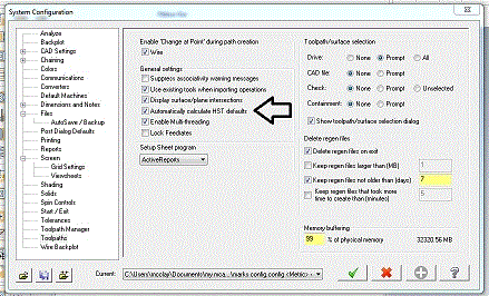
I just get a "setup error -f", when I try to run the executable.
same here.
-
We used to drill a hole similar except 1 1/2" dia (actually 40mm as I'm in land of metric) that needed a "cupped" bottom and hand dressed a HSS drill with the ball on it. It actually drilled really well, held size and had good swarf flow. Was in a lathe so was effectively self centring but might be worth a try. Hardest part was grinding the centre of the drill tip.
-
That's what its supposed to do, it's in your parts catcher

-
2
-
-
Only issue I see is that the steps are not getting cut to 0 stock in Z. Not sure if this is just a bug or if this behavior is intentional...I did have a similar issue with my suggestion of 2D HST with Area mill as well....no matter the settings used I could not get all faces to cut to 0 stock in Z in one op.
Like I said in my original post...I'm not getting into whether Esprit is better than Mastercam, or if Gibbs is better than Mastercam, or if Fusion360 is better than Mastercam...I merely stated that I've used features in software's other than Mastercam and that they improve workflow and if Mastercam was to implement some of these it may actually make your life easier. Some really got offended for some reason...
Good spotting Goooose, hadn't picked the depth issue as I just did a quick and dirty toolpath as I would approach it.
Can't get full depth either , weird !
Totally agree that MC has some catching up in certain areas and I would especially like to see it become more stock aware like a lot of other software, especially now that a lot of the programming is done straight from solid models.
-
It is possible to reverse a group of chains in each toolpath by using windows shift selection and right click reverse. This helps, but you still have to open each toolpath.
-
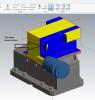
Without opening a huge can of Esprit vs Mastercam....
Mastercam really needs to up its game on toolpath creation from solids. Nobody wants to draw additional geometry just to get a toolpath outside of an 'open' edge. CAM software should be able to do this, and Esprit does (I'm sure there are others that do as well).
That being said though, could you not just use a 2D HST so you get the good chaining options but use an area mill path?
see my example, no extra creation , just smart solid face selection.

Mastercam OptiRough toolpaths
in Industrial Forum
Posted
On a side note I came across a bug yesterday in MC2017 that won't allow you to use 90% stepover with area mill toolpaths, just wont process. 89.9% or 90.1% works.
Has been logged.