cherokeechief79
-
Posts
622 -
Joined
-
Last visited
Content Type
Profiles
Forums
Downloads
Store
eMastercam Wiki
Blogs
Gallery
Events
Everything posted by cherokeechief79
-
thanks...our dials are set to dia it looks like your chart says the single side depth is .75 of the pitch. this is what I was looking for if its true. also we are measuring the thread pitch with different methods.we have a pitch mic,wires and a set of triangles . I don't have a chart for the triangles and I cant seem to find it on the internet. does anyone know where I can find the chart?
-
my students are making threads in a manual lathe and were asking me how deep to go once the dial is set at 0. I didn't have a good answer and said I usually bring it close and then thredmic it or see if a ring gage goes on.they were looking for something a little more specific like a formula or something. any ideas? we did learn that the flat on the tool should be 1/8 of the pitch.
-
I just did a very large engraving program with tons of text.im trying to get out and I'm getting the error.....you cannot close the application while a task is active mastercam;;OM post selected operations. I don't seem to be in the middle of posting or anything else? any ideas?i don't want to loose any of this file by forcing a shutdown.
-
I restarted the computer and it cleared it up.thanks guys. it worked fine in 2018 on the same computer.
-
thanks but engrave is like V carve.it does much more than just contour the geometry.
-
ive used this many times before and even recently without any problems at all.now when I select geometry and try to create the toolpath I get an error ive never seen before....."the message id 15006 from section me engrave_external process errors was not found in thr resourse dll" any ideas?
-
thanks I never knew that! this also has barcodes on it.not too hard to reproduce but tedious none the less. is there a way of bringing the whole page in as a pdf?
-
I usually recreate them to make them look great as you've said. there is an awfull lot of txt to recreate in this one though. ronc........can I import a txt file directly into mc without inputting it into the txt field while in the function "create text"?
-
I have to make a retirement plaque and itcontains only words but lots of them. the font is not fancy and probably just block letters of varying sizes. someone has already made the sample file for me in wordpad or a similar program. can I import this right into mc for engraving or am I going to have to rewrite the entire thing? I know I could use the raster to vector converter but I need the letters "crisper" than I would get by using the converter. thanks, mark
-
is this one continuous toolpath?how did you do this?
-
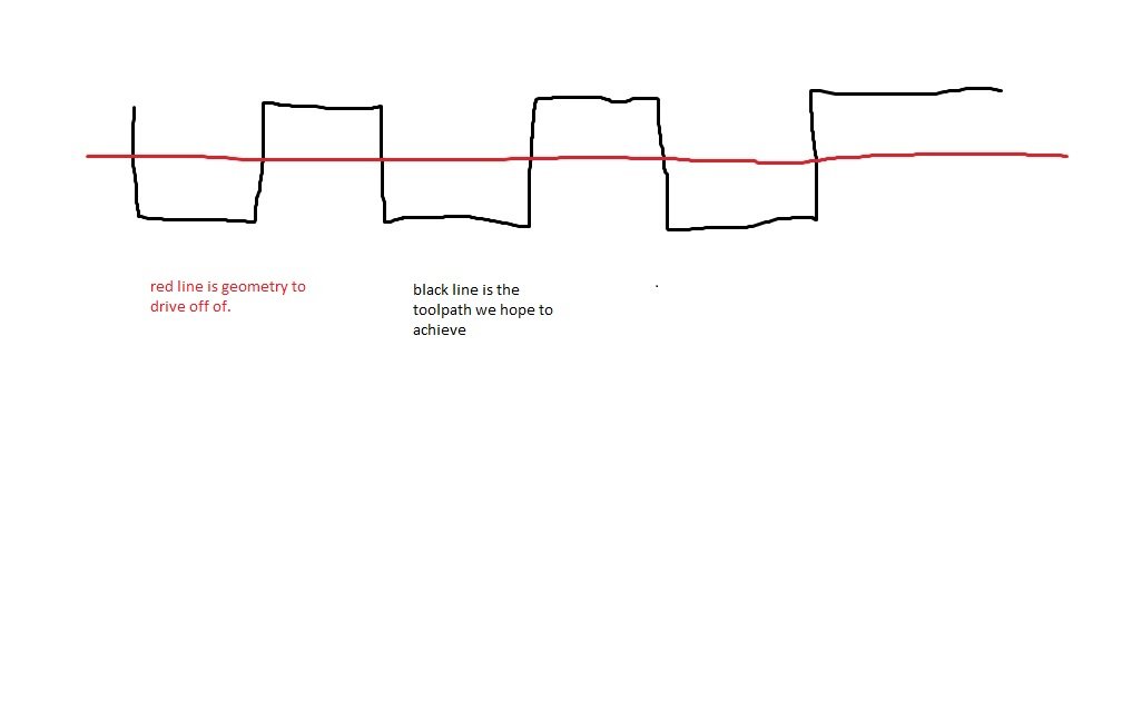
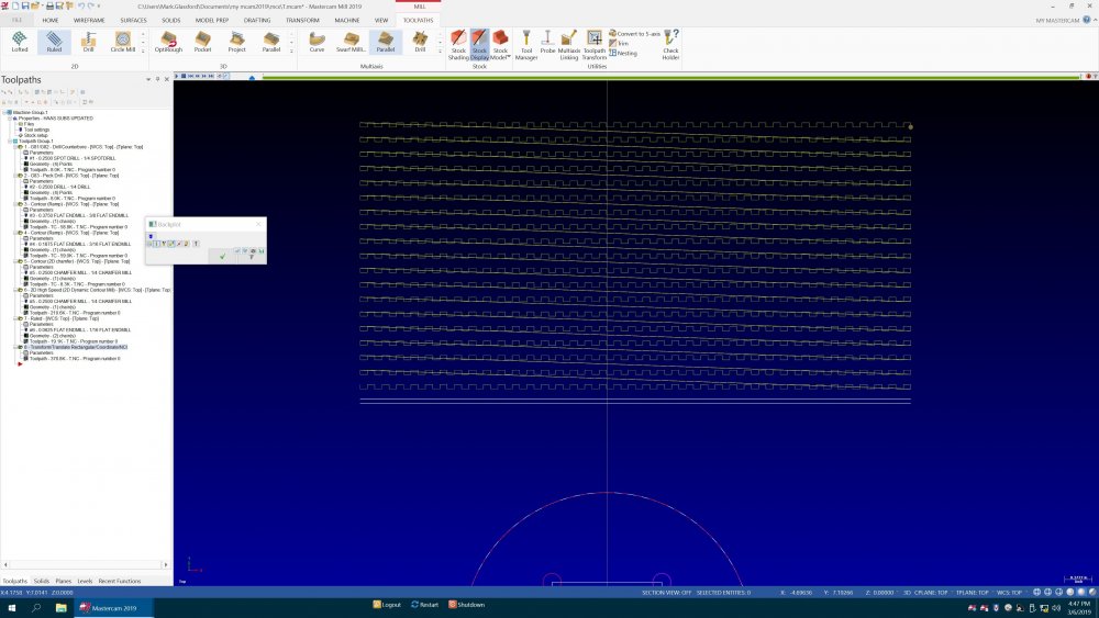
thanks guys.we will probably use the ruled toolpath between 2 lines now that we know its just not me that cant do this on a single line! this is the toolpath we want. ill just transform it and then trim toolpath to the shape we want and then do the same at 90 deg. this is an experiment in one of our powder bed additive machines.
-
thank yopu jayson, ive tried those.hopefully this pic will come thru.

-
sorry ......its the 2nd pic.the z needs to stay down .
-
just like your pic but left to right and use the driving geometry of a straight line. this is for an experiment in one of our 3d printers. very much the same movement of a weld bead along a single line but with a square wave type of motion.
-
I want to zigzag along a straight line 2 d.much like peelmill will go down a straight line but without arcs. is something like this possible without creating more than just one line?
-
we just got this new laser deposition additive mfg machine in. I'm going to be tasked with programming or training others because of my 5 axis haas umc 750 knowledge. this machine has a trunion table and I'm told mastercam has a post and a full simulation for this specific machine. any of you guys using one of these or something similar. I will have a lot of questions. thanks as always!
-
sweet there it is! thank you
-
yes but it creates kind of a spline that goes away after you exit the function. I would like to save it as geometry. it would work great for tracing images. I have a feeling it is raster and not vector based though.
-
ive never used this but saw a cowortker using it today. it looked like it worked awesome but I was curious if you could somehow convert the selecting method into geometry. it works kinda like a spline but much more flexible for freehanding geometry.
-
ive got kind of a crazy thread I'm trying to verify and I cant get it to work right. its a thread with 5 leads .verify seems to just show me grooves in the part. didn't older versions have a button called "tru thread" that was used to give a more accurate simulation? it seems to backplot ok.
-
our metalfab shop has a compact 750 press by this company. it has a small turret with a few different shaped punches. you can program simple things on the screen of the machine but it would take forever to program something very complex. I thought it would accept a dxf file if I created it in mc but after talking to the company they said it wont. can mastercam output code that this machine will read? they claim it can accept a program from a cam system that would output an asci file if it were properly posted. any ideas?
-
radius tool in verify poor results
cherokeechief79 replied to cherokeechief79's topic in Industrial Forum
wow! thank you so much! this has been bugging me for a loooong time. works perfect now. -
I have a simple 2 x 2 square that I'm putting a .25 radius around the top with a "roundover" tool. I created the tool myself and in verify the round it puts on the part is 3 different angles without anything at all that resembles a radius. I have the precision slider all the way up. in backplot it looks fine even in verify if I stop it ,it looks like the tool is only contacting in 3 points and makes straight lines between them. surely there is some way to bump up the precision on this. oops this is 2018 but looks the same in 19
-
i have to make a part that clamps around a ballscrew similar to the ones used on cnc machinery. the form needs to be nearly perfect to the form a ballscrew nut has, but without the balls and its only .500 on the id,a .200 pitch, and 1 inch long in stainless steel. any ideas on a tap of some sort or some type of a off the shelf tool with this form on it? its off center but if I had to somehow get it into a lathe I guess I could. tia .
-
thanks guys, didn't get to option 2 but the first worked fine.