


Chally72
-
Posts
501 -
Joined
-
Last visited
-
Days Won
33
Content Type
Profiles
Forums
Downloads
Store
eMastercam Wiki
Blogs
Gallery
Events
Posts posted by Chally72
-
-
34 minutes ago, sharles said:
Hey Dylan,
thanks for your help (and my resellers). They had me go in and delete the registry folders for 2022, uninstall 2022, and then everything went back in fine including the first maintenance update. All I had to do was save My Mastercam 2022 and Shared Mastercam 2022 folders so I didn't lose all my customized stuff. So I don't know if it had anything to do with permissions or not, but that worked.
Scott
Awesome to hear they got it sorted. Sorry you ran into trouble here!
-
 1
1
-
-
Had to chuckle at the shaded stock preview. Is it a graphical issue only or is it actually swapping the stock shape type in the background? This would be a good one to send in if the file saves in this state/is repeatable.
-
It definitely gets complex quickly if you have Stock to Leave values other than zero on your floor surfaces, too. If you're having to use specific increments/math on the stepups, the Adjust for Stock to Leave checkbox above the min/max depth field is there to automatically shift those min/max values by the Geometry stock to leave amount. It decouples having to make a stepup increment value change to get back to the same cut result if you end up going and changing the Floor Stock value by some amount.
-
19 hours ago, AHarrison1 said:
I find that putting a value into 'Stepup" nets the desired results. If I have no features that need ruffing above my Stepdown value then my Stepup=Stepdown.
If there are things like bosses or rads/chamfers then Stepup is about 10% - 20% of cutter dia
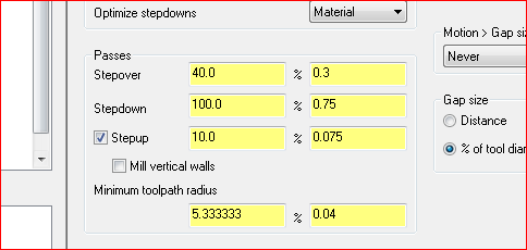
Putting a Stepup value in that matches the Stepdown value will basically tell Optirough to machine all flats that occur within the Stepdown window. Stepup values that do not match the Stepups will net you terrace steps that may or may not actually clear away material on ledges and such to the exact amount of Stock On requested in the geometry page.
-
 1
1
-
-
You can always define the slitting saw as a normal Slot tool, (with no nut) and then use the Import Geometry from File button on the Define Tool Geometry page and draw in a model of the tool that includes the nut on the bottom. The toolpath is calculated off of the yellow parametric tool definition of the slotting tool, but the Green imported geometry will be shown in Verify/Simulation so you can check the nut clearance. There's nothing any toolpath would be able to do to calculate clearance against the nut anyway during path generation, so this gives you the best of both worlds.
-
1
-
-
Hey guys,
When Mastercam installs, it extracts files to a user temp directory for use in the installation. (To be clear, not just the downloads folder. These are windows hidden folders such as User\appdata\Local\temp\) When installing an update patch, it goes and looks for those files in that directory. If the user account you're installing Update 1 under is a different one than the base installation was done under, and doesn't have permissions to access that temp file directory, Update 1 will be unable to get at the files it needs. Similarly, if the temp directory was wiped or files removed at some point after the original installation, or if there are permissions conflicts either during original installation or during Update installation, the Update install will likely be unable to continue and the Repair installation option will also likely not help.
The quickest way out in these scenarios, if you can't do the install under the same user account as the original or the files are gone, would be to uninstall and reinstall the base Mastercam version, and then go and run the Update 1 patch now that the necessary files exist and you know you have the correct permissions.
Hope this helps.
-
1
-
-
If you haven't already done so, try setting your NVIDIA settings for Mastercam to always use the dedicated graphics card. See my post in the thread below for a little guide to do so- substitute 2022 for 2018:
-
Everyone prepare for the transition from
"Here's the 43 steps to making this point-perfect multiaxis path" posts to
"How the heck do I cut this waspalloy material?!"
-
 8
8
-
-
In 2020 we started adding checks to make sure your machine definition build was a valid one. Before that, it was a bit of a wild west and you could build and set combinations that weren't technically complete or possible. Since more and more elements in things like posts are relying on Machine Definition data being correct, it was important to start flagging MD's that were set up incorrectly.
To confirm, this likely isn't a migration issue and going directly from 18 to 22 should not affect the outcome here. As thoughts right off the bat based on your picture, I see no table/spindle Components listed in your Axis Combination. to the right of the Axes.
-
2
-
-
3 hours ago, So not a Guru said:
Okay, that works. But in this video @Chally72 hovers over auto cursor points and the tool snaps into place. I can move the tool around, but it doesn't snap to any points.
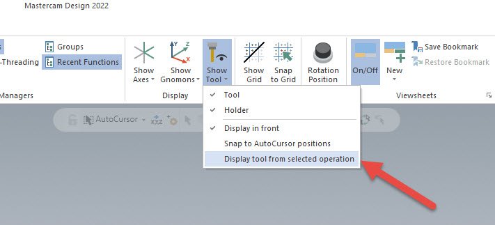
See that toggle choice right above the red arrow in my picture above- that should do it!
-
Don't forget this handy option in the Show Tool dropdown on the View tab:
-
1
-
-
All 3D HST paths support circle segment/Accelerated Finishing geometry, though of course you won't have much control over the contact point. For multiaxis, a Parallel cut pattern strategy, with a curve selection of the pocket outer extents, and passes set to spiral, should get you a good initial pattern that only leaves the outer pocket fillet/wall to deal with.
To get a lens tool to blend out into a perimeter radius in a pocket, I like to use a Tilt Tool collision control strategy to finish up. See how it affects the final passes on the part in the video below to get the lens tool all the way in the corner fillet even when my side tilt strategy for the rest of the path is calling for a different contact point. As long as your tilt strategy puts the tool reasonably close to the right position, this will tilt into the corner fillets very nicely and you'll be hard pressed to see the transition point.
A file would be the best way forward if you're still having trouble. Hope this helps!
-
1
-
-
Hey guys, thread here on the official forum with a workaround to get your colors back:
https://forum.mastercam.com/ShwMessage.aspx?TopicID=43441&Update=1
And summary:
QuoteThis has been logged as D-45750 and there is a work around.
The work around is go into the printing backstage menu (File, Print) and under options and check the box that says Color (shown below). You may have to restart Mastercam to get the Setupsheet to come out in color. Also Make sure the "Use Color" box is checked on the SetupSheet Dialog.
-
22 hours ago, Rstewart said:
Thanks, But none of those settings are working.
It just makes it harder to do a screen snippet for my set-up sheets. You cannot see the Axis Arrows unless you hover over it.
You should send this one in- that sounds like a graphical issue to me.
-
The standalone manager feature set and the capabilities available in Mastercam have slowly diverged over the years as a consequence of new features/functionality in Mastercam, interface limitations on the standalone manager side, etc. The natural consequences of this are there are growing lists things you can only do in one or the other, which is obviously not ideal. Eventually the tool team would like to ease some of these issues. Perhaps Rich will chime in on this thread.
-
 1
1
-
-
For filming and environmental reasons, we don't actually run coolant in our Manufacturing Lab machines at Mastercam. It makes the stainless work a little more challenging!
-
17 hours ago, Metallic said:
Hey Dylan I was just curious if this applies when creating planes via the "dynamic plane" option. Usualy when I am creating planes I have historically just dragged the Gnomon from the bottom left of the graphics window and applied it to my model in whatever orientation I want. I like this because I can do Autocursor to "face center" to get a plane on an angled face where I don't know the exact rotation angle.
Would the parent-child relationship respect that plane creation method if I then go rotating/mirroring models?
Thanks!
I made a little video to talk about creating, linking, and associating planes. There's a much better video coming on our official channel later this year, but this gives you all the important info about the cool stuff you can do with plane linking in 2022:
-
1
-
4
-
-
On 9/5/2021 at 10:27 PM, Fred @ Slate Industries said:
Scary at first , but it's what we're looking for . I don't know how easy it is to un tangle it back if needed...
You can easily edit a plane at any time and unlink it. You can furthermore have a parent plane that is associative to a piece of geometry, and then child planes that are all linked to that parent plane with different relative offsets, and if down the line you do something like Move or push/pull that associative geometry, all planes will correctly move to follow.
-
3
-
-
QC/Tech Support would probably like to look at that one too, if you can share.
-
1 hour ago, Müřlıń® said:
Guys I just had this happen to me.
My machine sim works flawlessly with all other files.
Since I set my inc save to 50, I found a saved file where the error does not occur.
It appears that it is not in the machine sim but the Mastercam file.
All the other files use the same XML file in the sim.
Please send this in to [email protected] with a part file and detailed description of the problem so we can take a look. Referencing this thread would help as well.
-
This is a perfect opportunity to take advantage of the new parent/child plane relationships that you can build in Mastercam 2022. Even if not associated to geometry, planes can be linked to each other such that when the parent plane is moved (translated/rotated) the child planes will all move with it.
-
2
-
-
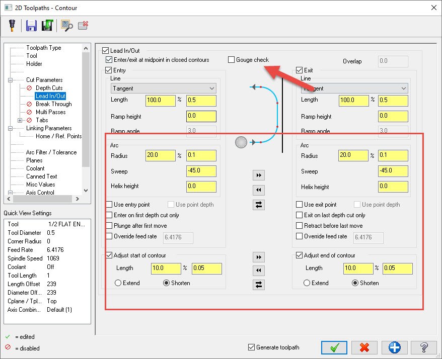
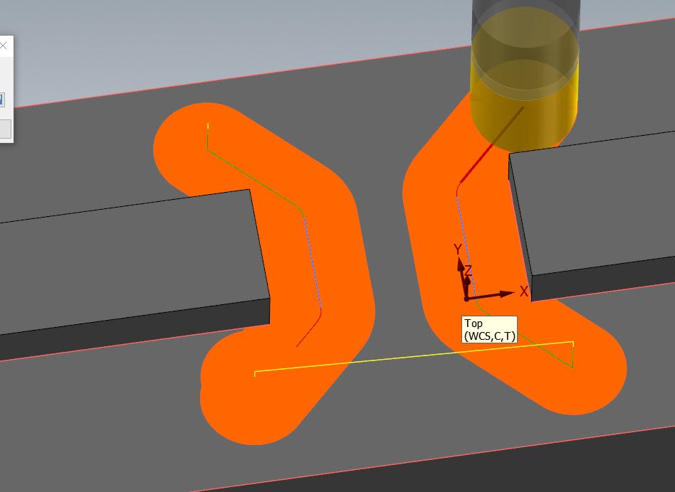
You can do this with a change to leadin/leadout while retaining just those edges as a selection. Just make the arc a negative number instead of a positive, and shorten up the contour length by a similar length as whatever radius you're targeting. See below for an extreme example- you can play around with parameters to get whatever break edge or roll you really want out of it. Make sure to turn off Gouge Check so that it doesn't automatically trim out what you're trying to do.
-
4
-
-
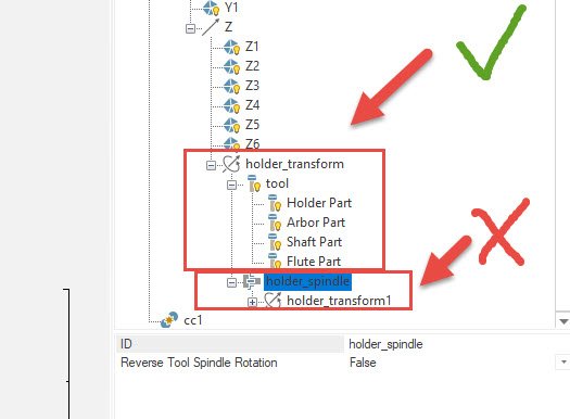
It sounds like you've got some issues with your custom machine definition. Machine Simulation is trying to get around them each time by applying a default definition when you launch into Verify or Sim, but it doesn't fix the issues with your machine file.
Right off the bat, I'd ask how you defined your tool/holder components in the machine. If you added the holder Spindle group component instead of the single holder transform group, this along with incorrect definition of direction/etc might lead to your error message:
-
2
-
-
4 minutes ago, Thee Kid™ said:
It could probably just test both and warn you of impending collisions for each scenario...
It cannot do this because this would be two branching paths of simulation. It also cannot ever truly match what your machine dogleg will look like, as that's based on individual axis acceleration curves- so even if Verify shows your dogleg clearing by 0.03", and thus doesn't trigger a warning, a slight change in actual machine acceleration could mean that your 0.03" of clearance now becomes -0.1" of clearance and you just clipped the part. Dogleg crashes shown in verify are at best, a guess at machine behavior defined by a fixed acceleration number in the machine def.
Best practice is really to never be introducing G0's in your toolpath while your tool is doing a "death star run" down in the valley between part features.
-
2
-
2
-
2022 Not impressed
in Industrial Forum
Posted
Like I mentioned in that thread- you're specifically asking for that behavior as a user. I don't understand what the behavior change would be- do you want the toolpath to ignore what you are asking?