


mikenaturalice
-
Posts
138 -
Joined
-
Last visited
Content Type
Profiles
Forums
Downloads
Store
eMastercam Wiki
Blogs
Gallery
Events
Posts posted by mikenaturalice
-
-
Thanks. Trying to avoid all those step files!
 I don't have 2017, not on maint anymore so using X8 and X9. I work with a guy that uses the creo cam package and he has to use solid models for his tool holders and I was extolling the virtues of Mastercam because it has so many tool libraries I just select when I am setting up tool, but no capto holders.
 -
Anyone have a capto c6 library of toolholders for MCX 8 or 9 they would be willing to share?
thanks, Mike
-
 4
4
-
-
The problem, in my experience, with those guys....
After many years, if they had any real talent, it's typically gone...and many who do work there, when a layoff comes, have no real skills, they can only follow an SOP
NO problem solving skills at all
That's been my experience, GE, Polaroid, Pratt & Whitney and several other very large places...
There are of course, sometimes exceptions to that statement....
Sounds like my place. They claim they want independent thinkers, problem solvers, etc, but every time you get shut down. It seems the only "thinking" allowed is from middle and on up management, We are just cogs in the machine. It is starting to be a struggle daily... well back to doing it the bosses way because he said so.

-
1
-
-
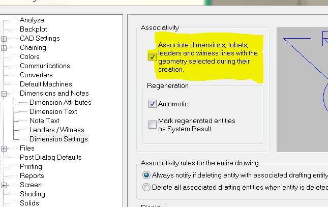
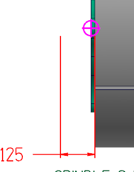
I am hoping this is a simple fix. I have my dimension settings as shown, with the box checked to make them assoiciative. So, my question is, it does not seem to work..?
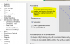
Or maybe I am mis-reading it? When I move something that has been dimensioned my dim text turns red, but that is it. I see on the dim bar there is an icon for update...
Ok weird. I just tabbed back into my MCX file and the dimension did update, but there was some delay for some reason? I actually moved it a couple times and each time it did not immediately update. I have the latest driver for my vid card (quadro K2000), any ideas of other things to look at?

-
Not sure if this helps, or is related to what you want to do. IME, I normally only used bounding box/center point tools when i wanted to mirror or rotate something, or know the center for stock or whatnot. Anyhow, I just recently noticed in X9 if you want to rotate or mirror something (assuming works with most xform ops), it will automatically create something like a temporary center point.
-
Colin, Doing as you described still plunges the tool into the edge of the material. It does get me a better toolpath however.
NOW with basic pocketing, how can I simply select a rectangle, tell it which edges are open, and pocket that rectangle? No other boundary wires frames, just one simple open ended pocket. I dont even need multiple depths. I will just create another pocket for another depth.
Just one double open ended pocket at one Z level. Thats it
I don't have much advice, except if you are dead set on doing it how you did it in Esprit you are going to have a hard time at it.
Can't tell how big your part is, but... If you import the model with edge curves all you would need to do is extend the lines the same as your tool diameter and then close them up, now you have a boundary at every level. Lots of ways to make this part, none of them being hard, or requiring much work IMO.
-
1
-
-
I vaguely recall knowing view sheets was a tool, but never used it. Just discovered what I could do with it this morning thanks in part to this thread, and another thread about creating section views using the view sheets. WOW! Awesome! thanks all

-
1
-
-
I'm not sure about where machine zero is on yours. I think it might be where the model was 'built' so it is possible the zero is at one corner of the table? Mine is easy, UMC-750 machine zero is top of table surface at the center. So my transforms are only need in Z most of the time. Occasionally with a bigger part that the zero may not be center of table I will have an X or Y value, but its rare. I opened my generic 4axis machine for simulation and mine is also not on center in Y, but Z appears to be correct, then would need to put an X offset according to where you are locating the stock. Y appears to be about 2" offset, no idea why. Sorry, don't know anything about editing the machine for simulation...
-
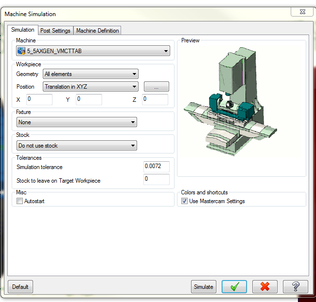
Have you used the Simulation Setup? It looks like you have a XYZ translation on your workpiece. This is useful for machines where zero in Machine Sim is the table, but you want to run in a vise. You can translate in Z to mimic the effect of using a vise.
Looks like you need only -X translation, to place the part to the left of the origin, on that particular machine.
That is exactly what I was thinking. Go to the simulation setup and setup your machine. There is a translation page to re-assign where xyz is related to the part.
-
and a biggy I forgot
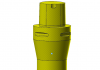
you can import vendor supplied step files to create tools and tool holders
this woks so so with tools ..mostly due to the quality of the vendor models
but it works perfectly for tool holders ..
I use a lot of Sandvik Capto tool holders and they come it exactly right
Have you used any of the twin tools? I just asked our reseller yesterday and he said they are not supported, but you can fudge the offset numbers to make them work. Also, what is the advantage of using an actual solid for a tool holder and/or tool? I always kind of thought having the premade libraries and not needing a solid was an advantage?? Have a guy using another software and he has to import solids for toolholders, which I think sucks, but maybe I am missing something...
-
Yes, the first stock model created in mcam runs fine. Save it out of verify and imports and generates path just fine. Bet when selecting it for verify the first cut makes it hollow, verify doesn't "cut" away. I'll send you a file when I get back in town if you want to see.
As I said, all settings are default. If I go in my stock model tool path and add an offset of .01in it works properly but also makes it cut where I don't want it too.
I have this problem sometimes too. What I do (probably not a great solution) is try and generate the stock model a couple ways and see if it improves. For example, sometimes I get different results by running the verify and saving as an stl vs using the stock model toolpath.
-
I'm curious, any users here that don't like the 2017 interface use any different softwares? I have not used 2107, not on maint.
 However, I watched a couple vids and the interface to me looks very much like Autocad 2017 and Inventor 2015 & 2016. I have not been on Autocad for a while so I am still getting used to Acad 2017, but I don't think it is bad... well not the interface part. Pretty much the same with Inventor, I don't find it so hard to navigate, although it is very different than Mastercam...
 -
I am guessing you want to stop before the reamer (in this case) to make sure the hole is to size from the drill, or to make sure the drill did not break? Do you have a probe for said machine?
-
i need two votes. i'll be upgrading my one personal windows system because, why not? we will not be upgrading or deploying any new windows 10 systems on the company network any time in the foreseeable future because, if it isn't broken it doesn't need to be fixed.
Huh... what? That is exactly what our IT department does.

It boggles the mind how much 'stuff' gets pushed around here. Oh hey we upgraded the online training classes! They don't work now, try back in 3 days. New password service! ...But try tomorrow after 1pm as it is down...

Oh yeah, have Windows pro7 here at work, Win10 at home. I don't mind 10, but I don't run any 'real' programs at home so can't speak to how reliable it is/isnt.
-
On my mill machine definition I have the box checked "support coolant using coolant value in post-processor". So I can only select flood, mist or thru-tool as on or off. In my lathe definition I don't have that box checked and I get all the options (flood, mist, thru-tool, custom 1-7) and the coolant button I have to select flood and i also get the option you see before, with, after. With the default 'before' selected my code looks like this -
T11211M8G97 S200 M03G0 G54 X0. Z.25G81 Z0. R.1 F.01M9G28 U0. W0. M05T11100M30%(Junk code ^ just to show formatting of coolant on/off). Are you just trying to clean up your code, or...? When I check the box like it is setup in my mill I get this -
T11211G97 S200 M03G0 G54 X0. Z.25 M8G81 Z0. R.1 F.01M9G28 U0. W0. M05T11100M30% -
For some reason files do save much more quickly if you turn shading off.
Mine does save faster with all levels on but shading off. Not as fast as if I only have one level turned on however. Sorry should have mentioned system specs before.
Using X9, Nvidia Quadro K2000, quad core I7-4770 @3.4GHz, 32GB ram, Windows 7 professional. I got this pc a couple years ago, maybe it is time for an upgrade? I think I have an ssd, but not sure. The hard drive is only 238gb so i think it is an ssd, is there a way to check? Saving and working on my desktop.
-
So I have a question about saving a large'ish file (14,184kb). I get about a 15-20 second difference between saving the file in question with all levels visible, and with only a few solids (etc) visible. Seems that would be graphics card related, but my question is why? Maybe has to do with generating a file preview or something? I have not done any investigation into the possibility of maybe it is just one particular level causing a problem, but my question would be the same - I am saving the file information, so how is that related to what is visible on screen?
I am wondering if maybe it would help when working on large files to have all but what level you are working with when programming? I will definitely try it next time an issue comes up, but if someone has the answer please educate me.
thanks, Mike
-
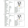
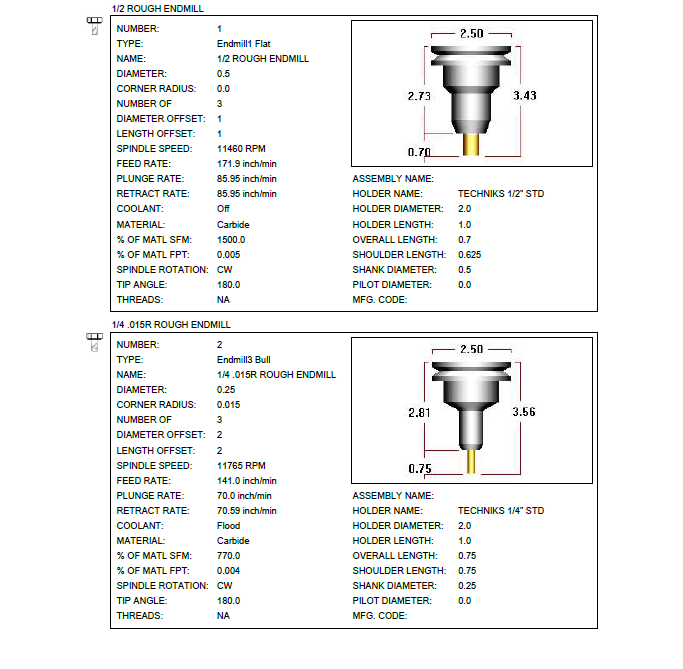
I select everything I want in my Op's Manager >> Right Click >> Tool List
I get them all
I do this but I include the pics. It shows the extension length of the tool which is helpful.
-
Terryh, are you using, or have you used other cad and/or cam packages? I am not on maint so I am stuck with X9 (not that I find it bad), but I have watched a couple vids on 2017. The interface looks very similar to Inventor if that means anything to you.
If all else fails, you should be able to open up X7 and X9 and you could just visually try and make them match if that helps you in any way....
-
Yeah, when I'm worried about how close it will be I revolve it. Never thought about draft, thanks for that one. That's really all I was getting at, it'd be a nice enhancement.
I often see drawings from before CAD times and there are frequently mistakes that cause interference or intersect where it should not.
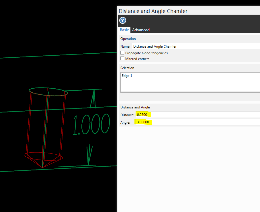
You can also extrude your hole to the depth you want it drilled to, then do a angle/distance chamfer on the bottom edge. So you want a 1/2-13 drilled to 1" deep and want to show the drill point correctly, extrude a .422 (or .4219 if you want) hole 1" deep, select distance&angle chamfer>bottom edge of hole>angle 31deg (or whatever drill you use) and distance of .211 (half the hole diameter).
I did a .50 hole in the example....
-
I have the Pro-e/creo translator. Meh. I think the idea was because our engineering department uses Pro-E and it would save the 'hassle' of them having to save it out as a step file. Step files are my personal preference, and stay away from iguess (iges) files, they are terrible!
-
Make a riser for the OTS and re-calibrate
Doh!! Never thought of that. Might have to do that next time I am caught up.
-
I am running one, 2014 model. I've done 4 axis machining, but not full 5 axis. I can't say as to the accuracy as what I was doing was not critical, the 4 axis machining part of the program was just cosmetic really. We got our post and machine sim from postability(?). I have had some problems with the machine sim and was told it was something that was being worked on, although I have not used the sim in a while so not sure if that got fixed. Nothing was wrong with the post, it worked fine, but sometimes the sim would show something goofy. The programming in MC is pretty straightforward for 4 axis and 3+2, not done full 5 as I said so i can't say how the 5 axis programming is. My post activates the G234 and G254 where/when needed so you can set your part up pretty much anywhere on the table, but be aware it affects tool lengths. I.E. if your part is on the extreme corner and you need to get to all 5 sides, one side the Z will be toward the high limit, and the opposite side will be at the low limit. I have a 5th axis vise and riser 'keyed' to the table so my parts stay pretty well centered anyways... One more thing, the OTS can not do really short tools, anything under about 3.25" gage length. Something to consider when buying toolholders. I use alot of 1/8" and 1/8" shank tools so I can't set any of my tools using an 1/8" or 3/16" solid holder (standard length holder), which also means I can't use the tool break check routine on them.
-
I think it is a post/machine issue, not really a mastercam issue. I think the last time I used that feature I got the M0 after the retract, but no spindle code afterwards so I had to manually edit that in. BUT, I think that was in X3-X4, no idea how well it works (or doesn't) now....

Tired of X9 already
in Industrial Forum
Posted
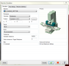
First thing that jumps out at me is the stock origin in the pic you posted.
X108.
Y39.
Z-6.
Are these coordinates correct??