


mikenaturalice
-
Posts
138 -
Joined
-
Last visited


mikenaturalice's Achievements
")
Newbie (1/14)
29
Reputation
-
The center looks wonky, but maybe they are trying to represent where the collet might be recessed into the nut a bit? (doesn't explain *concave* but..)
-
is it bad form to ask for a machine sim?
mikenaturalice replied to medaq's topic in Industrial Forum
If you have purchased the machine, and have made at least first payment, or down payment, don't see why you can ask for your copy of CAMplete now so you can start learning it. And as above, there wasn't a need to buy a post, or have a seperate MCX machine sim as CAMplete does all that for you. -
Alot of times I am programming 2 or 3 similar parts. The first one might take half a day or more, but I can then re-use toolpaths like Matt said and the next two parts might only take an hour each.
-
Thanks Colin! I was never really sure, but I thought it was doing something* with the Gcode as it did the posting "routine" the same as posting the NC code before the simulation would start. And I would say I am a novice user of 5 axis. *something is as technical as I can be on that subject LoL
-
I am not familiar with those codes, I am assuming they are for DWO, TCP, and 3d length comp? On the UMC750 it is G254 for dynamic work offset (3+2) and G234 for TCP (full 5 axis) and G141/G142 for 3d length. I can say all those functions worked fine using a post from Postability (?). Got the post and full machine sim for xx (cheap relatively speaking). And it was gcode sim pretty sure as it went through the posting 'routine' before it ran the simulation. It also gave warnings about a C axis rewind, which the UMC handles with a parameter to make it do the shortest revolution back to zero point and reset the C to zero instead of unwinding 1000 degrees or whatever. edit: Never had a crash with my machine and post (if you are wondering about the simulation factor).. just sayin'
-
That seems odd, not saying it is wrong as I don't know enough to be sure... I programmed a chamfer path (odd shape where I really needed to control lead in/lead out etc) and just manually edited a B90. into the program and it drew correctly on the toolpath. Did not get a chance to verify it ran 'cuz a mazatrol guy got it done in Mazatrol....
-
Also, you can try dopdf 8. For some reason here at work the cutepdf is blocked as malware. I am using dopdf and it works great with Mastercam.
-
Rotary axis substitution breaks C axis moves into many lines
mikenaturalice replied to wdg5555's topic in Industrial Forum
I got that type of output too using a post for Haas UMC750. Postability guys made it. Didn't seem to hurt anything, but the Haas rotary is by no means fast anyways. I will agree it is a little annoying to see 100's of lines of code in what could be 10-20, or something similar. -
Peck Drill output G0 and G1... not a canned cycle
mikenaturalice replied to DCOPE17's topic in Industrial Forum
Does your machine support the IJK format for peck drilling? Where I is the first peck, J is the decrease in peck size, and K is the minimum peck value. G98 G83 Z1.376 R.1 I.5 J.1 K.1 F11.7 edit: screenshot is from X9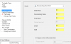
-
The only thing I would add to what Ron said, I did a similar project and left a few thou clearance in the keys, since the machine key ways were not perfect. That way, if you have a very long piece, you have some room to indicate the tailstock perfect. The key is leaving just enough that it is easy to indicate perfect, but not so much you spend 20 minutes indicating it in.
-
So anyone, think the OP will be back to report if any of these suggestions helped? Also, Colin G's post reminded me that there are two check boxes at the top for perpendicular and tangent entry. Might have those mixed up for whatever contour op you are doing.
-
If you think they are "limitless" in Pro-E our guy must not be very good LoL. Seriously though, I say that about Mastercam (limitless options), like you said tons of options just for lead in lead out. I would bet it is because we both are very familiar with 'our' software, yours being pro-e and mine being Mastercam. What version are you using? What are you trying to achieve exactly (a file will help)? I think the lead in lead out is very straightforward so I can't imagine what problem you are actually having, other than just not being familiar.
-
Creating Custom Tools from Geometry
mikenaturalice replied to Mickey@acceltool's topic in Industrial Forum
I've asked before, although I don't think I got a direct answer. For those of you using solid models for toolholders, is it just because you find it easier, or you want it exact, or..? I only ask because I thought the holder libraries in Mastercam were pretty good. They allow pretty decent modification too, however you can't make a radius. Back to the question of it being exact, anyone ever use a solid model from a company and find it is not the same as the solid file? -
Forcing MCX to select edges, etc
mikenaturalice replied to mikenaturalice's topic in Industrial Forum
You are right. I should have been more clear, I was actually specifically speaking of drafting LoL when I mentioned the CAD side of it! The actual CAD, creating geometry, solids, filleting/chafering said solids, is quite good!! I hate the fact I have to create a sketch plane in Inventor, then the tools just seem odd to me to create lines and things. Now the solid modeling in Inventor is spot on! Back on topic, thanks Thad for the heads up on creating a direct dimension (I'm lazy and always use the smart dimension), I might add that to my shortcut menu if I continue needing to dimension solid rounds. -
WOW! That is salty! I think Inventor Pro with the full HSM package (lathe and full 5 axis) is only like $400/month. Ya, that is $k a year more or less, but still. Besides, full blown MCX now (lathe, 5 axis) is probably$$-$$k + $k year for maint..?

