paulfell
-
Posts
133 -
Joined
-
Last visited
Content Type
Profiles
Forums
Downloads
Store
eMastercam Wiki
Blogs
Gallery
Events
Everything posted by paulfell
-
groove-MODEL-mcx.mcx-9
-
what do the control lines do?
-
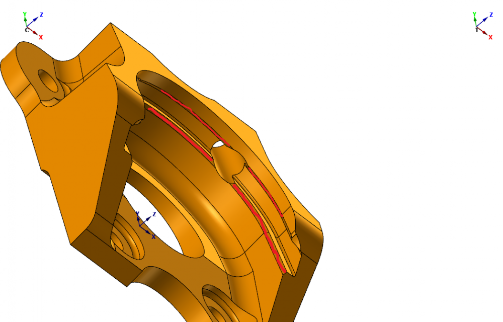
I have a chamfer to do top and bottom of a groove - in image - I have rough highlighted in red. I could scan with the tool i use for the groove, but interested in using 5 axis toolpaths more than I do at the moment. I think I'll manage the top chamfer - using an endmill with 5 Axis swarf toolpath (have done something similar before). The bottom one, can i scan it using a ballnose on a 5 axis path so ballnose is always approx perpendicular to chamfer plane - and will not hit other areas of the component. Maybe quite simple - but not overly familiar with 5 axis paths - anything to point me in right direction would be appreciated - thanks
-
Thanks for reply, no access to Mastercam until next week now - without looking through the toolpath options I am not entirely sure what you mean by stock model ?. I used method described n thread - saving an stl file from stock produced by previous ops - then picking it as a CAD file - I assume from replies there is another way - anything to pint me in the right direction on other method would be welcome - I will give it a go next week - thanks
-
Thanks all- I used opti rough toolpath- using stl model, I didnt understand about making my stock from stl on a level, I did put it on a level anyway for reference. but saw no option to pick it from the level - only to select the file ( hope that makes sense). Anyway - it worked well
-
using x9 - can i use opti rough with stl file saved from surface pocket toolpath - this toolpath is already a couple of hours into cut - so will have to go with it now. Liverpool is great - massively improved city over last 10 years - where does it say where im from ?
-
I have just tried surface restmill - it wont generate a toolpath - comes up with error - ''cant extract at least one solid face''
-
so I cant use surface restmill with surface rough pocket?
-
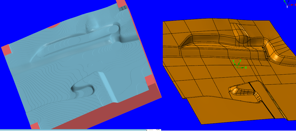
I have roughed a steel billet (approx 30'' square) as per pic attached, I have used Surface Rough Pocket with a large Facemill. I now wish to continue with roughing using a smaller tool, I know there is a method/ toolpath which takes into account previous ops - this will obviously save a lot of roughing time. I have never used this method or toolpath - although I know it can be used, could somebody point me in the right direction on how to do this ( I will then research it more before using it ). There maybe another method of saving stock model and using that as stock for next toolpath ?. Any advice on method/ toolpaths would be welcome - thanks

-
ha ha. thanks. caps is my OCD
-
I WAS THINKING OF THAT AS A SOLUTION. WITH ME HAVING TO MAKE A MALE AND FEMALE PART I WOULD PREFER TO HAVE MODELS. AGAIN THANKS
-
OK. I'M NOT USED TO DEALING WITH SHEET MODELS. ALTHOUGH I HAVE TRIED TO THICKEN WITH NO JOY. AS IT KEEPS TELLING ME THICKEN OPERATION FAILED
-
WITH IT BEING A SHEET MODEL IT WILL NOT ALLOW ME TO THICKEN. I WILL HOWEVER TRY AND MAKE IT A SOLID MODEL AND THEN THICKEN. THANKS
-
I'VE ACTUALLY TRANSLATED THE PART, WHICH SEEMS TO HAVE SORTED IT. I'VE DONE A FEW CHECKS AND SIZE SEEMS TO BE CONSISTANT. FROM A MACHINISTS POINT OF VIEW I INITIALLY DIDN'T THINK THIS WOULD WORK!! THOUGHTS???
-
I'M LOOKING TO MODEL UP A PRESS TOOL. MALE & FEMALE PART WITH A 0.048'' GAP IN BETWEEN. I ONLY HAVE THE FEMALE MODEL IN A SHEET FORMAT BUT WISH TO UNIFORMLY MAKE THE MALE PART. WHICH IS THE BEST WAY TO DO THIS?
-
so when changing versions - how do i reset my preferences which are saved in config - is this just a no for x9- 2017 ?
-
Can I copy my config file from x9 and put it into 2017 ?
-
Thanks - I didnt know about chaining a point either - like the look of circle mill - very useful info- thanks
-
Never used Circle Mill before - once i'd found the setting to start on centre - that did it - thanks - does circle mill have any other advantages over contour ?
-
I am trying contour method suggested - ok in theory - but tool is 16MM dia, and smallest part of sphere is 17.3mm dia. so not much room to get tool in and out - at the moment tool would damage bore as it retracts , and even though the lead in is adequate at top at bottom of bore - once machining centre - it hits smaller part of sphere as it retracts - I need to either stop it retracting or keep it on centre as it retracts - any ideas ? see pic for op and some settings
-
no 3d comp on control - I will give the geometry off surfaces 2d contour method a go - still trying to workout if the theory is correct - but will give it a go
-
macro we use rotates around a circle centre in Y & Z (in 1 degree increments) allowing for rad of tip - then changes circle centre to X & Y and mills 360 degrees - changes back to circle centre in Y & Z iand repeats process - so theory is good - we just work to a go/nogo ball - not sure what an air gauge is? . Not familiar with 3D Comp Chook - will investigate more - what do you mean by options for 3D comp ?
-
The screenshot shows a Spherical Bore - we machine various similar parts with difference size bores. These parts are programmed using Mastercam for everything apart from the bore, to do this we insert a pgm to finish bore, which is editable to hold exact size of the bore, we use a Heidenhahn pgm using variable q values ( similar to # values on Fanuc), we use a depo cutter (similar to Lollipop Cutter). This works well and is fully adjustable. Is there a way in Mastercam to machine a spherical bore, with some control over the size ( i.e. Cutter Comp ) . I know i could just repost and run with different stock allowance to adjust size - but this requires a programmer to be on hand when job is running - rather than an operator adjusting it at machine, I dont think there is a way - but thought i would ask

-
if i use check - it quite often leaves some parts of surfaces unmachined - it doesnt using containment - i will look into blend - never really used it - thanks
-
Thanks - I did improve by lower cut tolerance & changing containment - its now a lot better - but still not right - a surface toolpath shouldn't dig into a drive surface - but this does?