


ahaslam
-
Posts
272 -
Joined
-
Last visited
Content Type
Profiles
Forums
Downloads
Store
eMastercam Wiki
Blogs
Gallery
Events
Posts posted by ahaslam
-
-
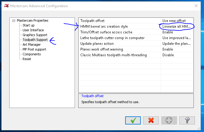
Just a guess, try linier arcs or pull your advanced config and shut off HMM Kernel arc creation style. I think that was added after X6.
-
 1
1
-
-
1 minute ago, JohnW@Kauffman said:
If you've gotten the hang of 5 ax curve, you'll see some familiar data fields and functions. Sometimes I have to play around with tool axis control to get the results I want. Morph will require some wireframe, or surface curves or solid edges to pick "from" and "to" geometry, along with the surface or solid face you want to cut. I don't do a lot of surface machining, most of my work is trim/drill, but when we cut a mold, I get into the multi axis surfaces paths on some of them.
Ha, John beat me to it by like 30 seconds.
-
If you are already familiar with curve, the Morph and Flow are fairly similar. Selecting geometry and tool axis control are primary. I would avoid setting up roughing, linking, and other secondary functions until you have a path that generally flows the way that you want. When first playing around with the paths, set quality and stepover to higher numbers. This helps to allow quicker regen because it may take a few tries.
-
1
-
 1
1
-
-
Okay, now I follow. I did it a bit different, I changed my probe routine so that my tools would be shifted to center of table from the touch off. I also came up with a slightly different way to calculate it but in general it is the same concept. Please note, on the Okuma MB-5000 I found that if the machine over travels inside of the macro it will not alarm out. My macro told it to move to Y-.5 and the machine made it to Y-.43 and started the G81. Kinda scary if you don't watch it. When I get the chance I'll post the in position check that I added.
-
I think I am confused on the CDEG=[SDEG+-INDX] (CACL DEG). It seems to flip flop I go from a ZMPS positive to a ZMPS negative. Have I done something wrong there?
-
The only issue I have is that the MU series is a 5 Axis machine. OO88 is setup to run on the A/C axis and is heavily integrated into the control. So even if he got his hands on the file I can't honestly see proper implementation of the sub. I'm not saying it's not possible, just that I have been down this road and this custom sub was my solution.
-
I have some already put together for just that. I had do give operators a list of rotations to manually program indexing haas box... Thing... Pm me if you want to see an example post because I'll forget to send it by tomorrow.
-
They have made some pretty massive changes to the ops list. The quick and easy method to look at a good list is to check out the mpmaster.pst from this site. They did a pretty good job of breaking it down. The changes are listed in the new pdf you can get from the reseller. The new list includes stuff for the new hsm surfacing and dynamic stuff. Glad to see this post is still relevant though.
Cheers!
-
I don't have anything specific to the laser but I assume it runs with a G31 just like most add-ons. If so, I have some english articles that can get you up to speed pretty fast. Google translate should do a fair job of fixing the language gap. PM me if you are interested. I try to keep my FTP free.
-
Ha, that's interesting. I just finish reworking an okuma macro to do exactly that today.
Try my sub. To heck with that OO88 thing. Let me know if you have any issues an I would be happy to help out.
Good hunting.
-
Hey team, just a heads up, I found this macro to have a few issues in its function. My initial setup or application of it maybe at fault but I assume I am not the only one. I re wrote the sub based on this macro for an Okuma MB-5000. I also created a function in the post for the macro to be used at all times. The format of the code is
G115 PH=1 PX=0. PY=0. PB=0.Where G115 calls sub OROT, PH=# will reference your work offset (G15 H#), PY=# & PX=# is the start position of the tool and PB=# is your rotation to.
When you first setup a part, set your X, Y, and Z in your work offset relative to your center of rotation. Once the sub is called it will shift your new X,Y,Z, and B to theatrical zero relative to center. I do not currently have a function for shifting the zero if your center of rotation is not X0, Z0 but I could help put one together if need be. Once the sub is ran the machine will be reading from G15 H200. Here is the sub
OROT(115)
(PH = WORK OFFSET TO BE USED FOR CALC)
(PX = MOVE TO X)
(PY = MOVE TO Y)
(PB = MOVE TO B)


INDX=PB (SAVE B POSITION)

XDTA=VZOFX[PH] (PULL X POS)
ZDTA=VZOFZ[PH] (PULL Z POS)

CHXP=SQRT[[XDTA*XDTA]+[ZDTA*ZDTA]] (HXP FOR CALC)

XDEG=[ASIN[XDTA/CHXP]] (START DEG FOR CALC X)
ZDEG=[ASIN[ZDTA/CHXP]] (START DEG FOR CALC Z)

XCDG=[XDEG-INDX] (CACL DEG X)
ZCDG=[ZDEG-INDX] (CACL DEG Z)

XDTN=[SIN[XCDG]*CHXP] (NEW DELTA X)
ZDTN=[SIN[ZCDG]*CHXP] (NEW DELTA Z)

VZOFX[200]=XDTN
VZOFY[200]=VZOFY[PH]
VZOFZ[200]=ZDTN
VZOFB[200]=VZOFB[PH]

M403
G0 G90 G15 H200 X=PX Y=PY B=INDX
RTS
Lastly, for the Mastercam side of things.
Switch allows to turn on and off as needed in the post
g115 : 1 #G115 swtitchUnder the ptlchg_com post block I have
        pcan1, pbld, n$, *sgcode, *sgplane, *sgabsinc, *sgfeed, "G40", "G80", e$
          if g115, "G115", [if not(index), pfwcs], pfxout, pfyout, pfcout, e$
          else, [if not(index), pwcs], pfxout, pfyout, pfcout, e$
          pfspindleout, [if gcode$ = 1, *feed], strcantext, e$
        if lock_codes = one & not(index) & rot_on_x & cuttype = 0, pbld, n$, *slock, slockcomm, e$
Under the ptlchg0$ post block
            if g115, "G115", [if not(index), pfwcs], pfxout, pfyout, pfcout, pspindleout, e$
               else, [if not(index), pwcs], *sgcode, pfxout, pfyout, pfcout, pspindleout, e$
Under pfwcs Post block
            if g115,
            [
              g_wcs = workofs$
              gh_wcs = g_wcs, !g_wcs *gh_wcs
            ]
            else,
            [
            g_wcs = workofs$
            *g_wcs
            ]
Then for forced output I added this to give the G115 its location
pfxout          #Force X axis output
      if g115 & ((wcstype > one & workofs$ <> prv_workofs$) | (tlplnno$ <> last_tlplnno) | retractflg), [xpx=xabs, *xpx, !xabs, !xinc ]
         else,
         if absinc$ = zero, *xabs, !xinc
         else, *xinc, !xabs

pfyout          #Force Y axis output
      if g115 & ((wcstype > one & workofs$ <> prv_workofs$) | (tlplnno$ <> last_tlplnno) | retractflg), [ypy=yabs, *ypy, !yabs, !yinc ]
         else,
         [
         if absinc$ = zero, *yabs, !yinc
         else, *yinc, !yabs
         ]

pfcout          #Force C axis output
      if index = zero & rot_on_x,
        [
        if use_rotmcode & (fmtrnd(cabs) <> fmtrnd(prv_cabs) | sof), *sindx_mc
        if g115 & ((wcstype > one & workofs$ <> prv_workofs$) | (tlplnno$ <> last_tlplnno) | retractflg), [cpc=cabs, *cpc, !cabs, !cinc ]
            else,
            [
            if absinc$ = zero, *cabs, !cinc, !cout_i
            else, *cout_i, !cinc, !cabs
            ]
        ]
I hope this is of use to others. I love the ability to slap a part on the rotary, probe it once and be ready to run with out a worry.
Oh, something else to mention. If you leave your work offset as zero or -1 in Mastercam you will get an alarm at the machine. I have been meaning to add something for that. Also, never set your work offset as 200 when using this sub... bad things will happen...
-
1
-
-
I haven't ever worked with Sodick but I would be happy to take a look and see what you have. Have you opened the post and found the logic for the "C###" output? If so, copy and paste the whole post block on the forum as well as any post blocks it might link to. Then we can take a look at why its not reading the 903.
-
On 6/26/2017 at 4:27 PM, ajmer said:
check the stepover of the copied operation
sometimes it doesn't update and keeps the large stepover of the initial roughing tool
I did go back through and check all that prior to posting this. Did you not have the same issues?
-
I might have found a bug in 2018. Does anyone want to take a look at this for me? In the op2 group, I created an area tool path then decided to copy the toolpath to do a rest machining operation. The copied tool path has been rendered useless. Even after unnecessarily reselecting the geometry I couldn't get a valid path. The bug stands out when you click "preview chains" button (reference the Z2G). I will work around by creating a new path as opposed to copying but has this been reported already?
Thanks,
-
I would love some suggestions on this part. I am planning to run it on an HMC with a true 4th axis and an Okuma Control. Normally I would just dump a bunch of planes into the program and load it up with tool paths but I have some time to play around with this. I have multi axis toolpaths available on my hasp so pretty much the sky is the limit. The part is aluminum and about a ten inch dia. Thanks in advance for any ideas.

-
I checked my OCHG. Everything looks good. I tried initializing my libs to clear everything. I did a hard restart directly after that and it still gave me the error. Any ideas?
-
26 minutes ago, C^Millman said:
Chris, I tracked them using a string process you could go about 99 deep and have no issues. You could override them using mi and mr if you wanted to. It would have been around 2007 or 08. I could dig up that post if you would like to take a look. It is crude, but it did a decent job.
I would love to see that. You know, just to drool over.
-
3 hours ago, C^Millman said:
Did you call you local Machine Tool Rep's service or applications department?
Sorry best I got.
Yeah, in short, he hasn't been able to answer my question.
1 hour ago, YoDoug® said:Error 5262 says that that file is already registered when the control is trying to register it. Do you have that OCHG macro in multiple .LIB files. If so that is most likely your issue.
I might, I compiled a catch all .lib. I thought I removed the OCHG but maybe I left something in there on accident. I'll look into that. It should still load my other .libs, right?
-
I have been searching around for information on this for a few hours now. I feel like I keep coming close but I can't find the right info so I am hoping you guys can help me out. I have changed a few things, added a few things, and removed a few things from the library programs in an Okuma OSP-P200 HMC. At some point, I did something to where now the autoload library isn't loading the files when the machine starts. I have to go in and manually load the .lib files each time I restart. I also have been getting an error (see attached image) related to ochng, a file that I am not using anymore. How do I update the autoload library function? Also, I'm really new to Okuma and would love if anyone could point me in a direction of better documentation than what came with the machine. Thanks,
![20170607_090737[2].jpg](https://www.emastercam.com/uploads/monthly_2017_06/59383ad6f0b0a_20170607_0907372.thumb.jpg.58299111952860415569af28c439f8a5.jpg)
-
If you have a bit of know-how with posts the Generic Fanuc 5X mill.pst that comes with Mastercam can be modified pretty heavily. With that said, it's a decent undertaking in terms of time and commitment. Most of the hidden stuff in the .psb is of little concern to you as the end user. It's just formulas for calculations that rarely needs modification. The hardest thing will be setting up the switches and mapping for your machine. Is this the first multi-axis machine in the shop?
-
C:\Users\Public\Documents\shared Mcam2017\mill\Ops has your .defaults in it. That's where Mastercam pulls the general dialog but keep in mind that something will change based on Dia of the tool such as step over or step down in the dynamic tool paths.
-
Could you put a Z2G file on here with what you have? That way we aren't starting from scratch. Thanks
-
Huh, I'm new to Okuma so I'll have to look into that. Thanks.
-
The Cas? Tell me more about this CAS?
![20170607_090737[2].jpg](https://www.emastercam.com/uploads/monthly_2017_06/59383ad617de6_20170607_0907372.jpg.f25fff36d038a23affd18f119d7b3bfe.jpg)
Live 5axis programming question
in Industrial Forum
Posted
Also, Swarf may be a very effective tool path for finishing. I would think using Guide curves with a taper mill and turning on Pattern slices with a forgiving DOC would give a solid path for finishing.