


ahaslam
-
Posts
272 -
Joined
-
Last visited
Content Type
Profiles
Forums
Downloads
Store
eMastercam Wiki
Blogs
Gallery
Events
Posts posted by ahaslam
-
-
I figured out the issue. Added a check to fix
pcout           #C axis output
      if index = zero & rot_on_x,
        [
        if use_rotmcode & fmtrnd(cabs) <> fmtrnd(prv_cabs), *sindx_mc
		if fmtrnd(cabs) <> fmtrnd(prv_cabs),
		  [
            if absinc$=0, cabs, !cinc, !cout_i
            else, cout_i, !cinc, !cabs
		  ]
        ]
-
Glad to help.
-
I looked over the post. First off, this is a pretty old post. There is nothing wrong with that, it's just a little harder to work with and is lacking a few of the newer features. I see that Axsys was the post writer and they had modified it last year. Have you had the chance to bring this up with them? I hope they would be able to fix the tool change thing without throwing more money at it. I'm not seeing anything that is jumping out at me on it. When you post multiple tool paths, do you see an M98 P2? As for the arc issue, are you using a wear comp for the post? The G41/G42? I'm curious if the mazaks are having issues with arc length under comp. If so, would it be possible to remove the G41/G42 and just use the T0101? Again, not a lathe guy so I'm kinda swinging in the dark on this one.
-
That's a pretty in-depth request. For the arc thing, their will always be a small amount of error between the actual and the definable. What is the control you are using on your machine? What is the error you are getting? You could try breaking arcs as a temporary fix but it will potentially affect your surface finishes. I'm not much of a lathe guy but that might work.
As for the tool change issues. It would be hard to really get to the bottom of this without knowing more about the post. Where did you get it? I could glance over it if you want to PM me the post but no promises. Have you contacted your reseller about the issues?
-
I agree with Jparis. Although that may not be what you wanted to hear, a multi-axis machining post is a lot of work that even advanced users don't mess with too much (a good chunk is locked from standard users). It's kind of the same thing for the Sim.
-
If you do want to do the .txt file thing, creating a sub file isn't too hard. Check out the subout function in the MP Doc. There are pros and cons to both active reports and using the post to create setup sheets. I work with a lot of older gentlemen that hate the fancy stuff. Once I dumbed down the active sheet up sheets to their liking I was basically looking at a .txt file.
-
What post are you using? Something isn't updating right. Can you post the full array of the sgdrill that shows the fstrsel? My first thought is that maybe the count got messed up somewhere.
-
I put together a post that will let me use the dynamic rotation on my HMC but I am stumped on something. At the start of the tool path I have a pfcabs that will force out the B move based on a bit of logic. That part works fine but when it hits the pcabs (as well as the x y and z for that matter) it posts out the abs again even though I have a !cabs in my pfcabs. All of this is based on the mpmaster post from IHS. I did run the debug and stick a watch on my cabs. cabs and prv_cabs match as the post enters the pcabs block. Here is a look at my code.
ptlchg_com
  		  if g115, "G115", pfxout, pfyout, pfcout, e$
		  else, [if not(index), pwcs], pfxout, pfyout, pfcout, e$

ptlchg0$
  	  	  if g115, "G115", *sgcode, pfxout, pfyout, pfcout, pspindleout, e$
		  else, [if not(index), pwcs], *sgcode, pfxout, pfyout, pfcout, pspindleout, e$


pfcout          #Force C axis output
      if index = zero & rot_on_x,
        [
        if use_rotmcode & (fmtrnd(cabs) <> fmtrnd(prv_cabs) | sof), *sindx_mc
      if g115 & ((wcstype > one & workofs$ <> prv_workofs$) | (tlplnno$ <> last_tlplnno) | retractflg), [cpc=cabs, *cpc, !cabs, !cinc ]
	        else,
		    [
            if absinc$ = zero, *cabs, !cinc, !cout_i
            else, *cout_i, !cinc, !cabs
			]
        ]

pcout           #C axis output
      if index = zero & rot_on_x,
        [
        if use_rotmcode & fmtrnd(cabs) <> fmtrnd(prv_cabs), *sindx_mc
        if absinc$ = zero, cabs, !cinc, !cout_i
        else, cout_i, !cinc, !cabs
        ]
Thanks in advance guys.
-
On 4/21/2017 at 0:25 AM, Günther Massimo - GMCCS said:
I'm using Visual Studio Community. It's free.
")
I stand corrected. This is what I read that confused me on this.
mastercam-chook-introduction.pdf
"In order to develop your own C-Hook for Mastercam X9 or Mastercam 2017 you will need Microsoft Visual Studio 2013 Professional or higher using the 'v120' Platform Toolset. The free edition of Microsoft Visual Studio 2013 Community Edition will also work just fine. If you are targeting Mastercam X8 you will need Microsoft Visual Studio Professional 2012 or higher using the 'v110' Platform Toolset. Note: You cannot use the free Express versions of Visual Studio as they do not have the required MFC support."
-
 1
1
-
-
I haven't seen a quick way to know the tool path length using the MP. A cheat you could use for the time being is by looking at the backplot's info tab. That will tell you the length of feed/rapid time. Adding a "fq" function into your post for user input would allow you to have that info in the MP at the time of posting. There might be a way to pull the info seen in the backplot via C-hook/Net-hook but that's way over my head. If so, you could easily pass that info into the post processor at the time of posting without using a manual input. I do hope someone else knows an easier way though although Colin would have been the first I would have asked. Good Luck.
-
Something to note. You can use the C#/VB SDK in Visual Studio 2015 all for free. If you want access to the C++ SDK, you will need to have the paid version of Visual Studio.In order to develop your own C-Hook for Mastercam X9 or Mastercam 2017 you will need Microsoft Visual Studio 2013 Professional or higher using the 'v120' Platform Toolset. The free edition of Microsoft Visual Studio 2013 Community Edition will also work just fine. If you are targeting Mastercam X8 you will need Microsoft Visual Studio Professional 2012 or higher using the 'v110' Platform Toolset. Note: You cannot use the free Express versions of Visual Studio as they do not have the required MFC support.
-
1
-
-
I'm definitely overthinking it then. Thank you.
-
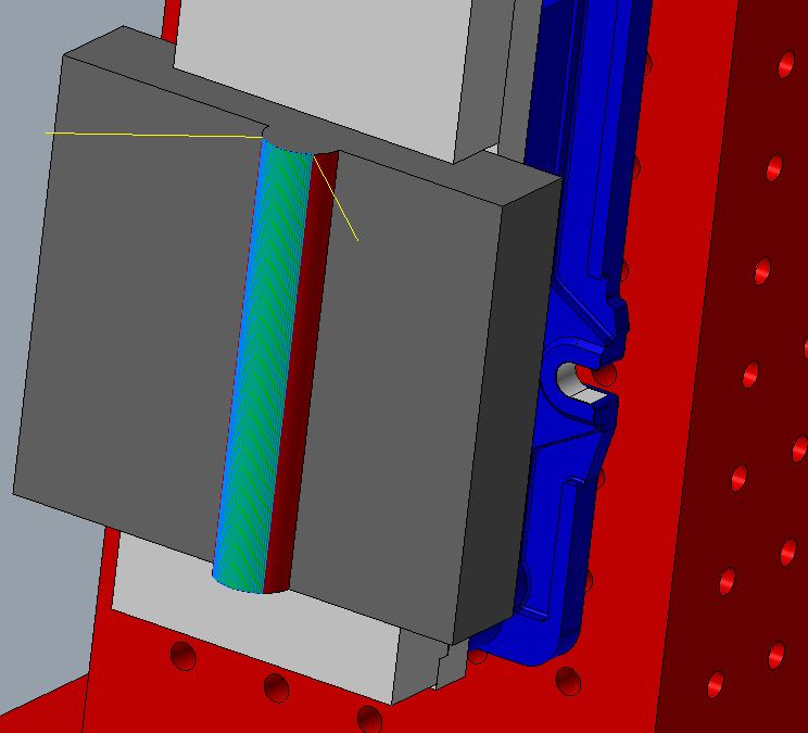
I'm trying to machine a cylinder on a tombstone setup. In the image, you can see I used a multiaxis flowline to machine the front face of the cylinder. I'm happy with that tool path but I would like some advice on the next toolpath. I want to do some type of multiaxis swarf surfacing. I highlighted the surfaces I intend to swarf in red. I've tried a few tool paths but can't get anything close. Could someone give me a hand on parameters to get an output about the B axis?
Thanks,
-
Wow, okay, proper answer on my end is, I don't know. I'll just watch from here but now you have me interested. I did find a pretty neat video that breaks down the formula but I would really like to see what jlw has.
-
OHHHHH, okay. Well geez, you just took all the fun out of it. I'm not sure if I am going to start giving the right info but here it goes.
The simplest way to define points on a sphere is to think of the points like a bolt hole circle. so calculate a 3 point circle at the radius of your tooling ball then toss one point at the top. For example, on a .500" tooling ball you would have
X 0.0000 Y 0.2500
X 0.2165 Y-.12500
X-0.2165 Y-.12500These would be you hit points. (your G31 lines)
To find your start points such as .25 (or what ever) away from the ball, just calculate a bolt hole circle that has a radius .25 larger.
X 0.0000 Y 0.5000
X 0.4330 Y-0.2500
X-0.4330 Y-0.2500To calculate this by macro you will have to build an equation using the math functions built into macro-b. It has all the trig functions available.
The 4th point (being z) is pretty self-explanatory.
I'm just about to leave work so when I get in tomorrow I can show you that part if you want but the machinery's handbook has a pretty good breakdown on how to do it. Gotta run.
Edit: So now that I am home rereading your post and realizing something, Are you asking for the points on a chord of a sphere? If you are only using a section of the sphere then you might have more issues with error based on how small the ball is but you can calculate points of a chord with trig on the machines.
-
I'm a little confused. Are you just looking for a Macro to find the center of a sphere? Will you be running vectors parallel to an axis (such as in z) and are your machines a table-table configuration? Also, how close will the repositioning of the tooling ball be? +/- .125?
edit: Actually, a picture would be awesome. I am happy to walk you through a few things on macros (because they are freaking awesome) and show you how to build a probe cycle I'm just not sure what's going on yet.
-
Fellas,
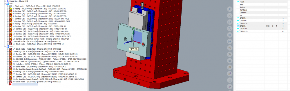
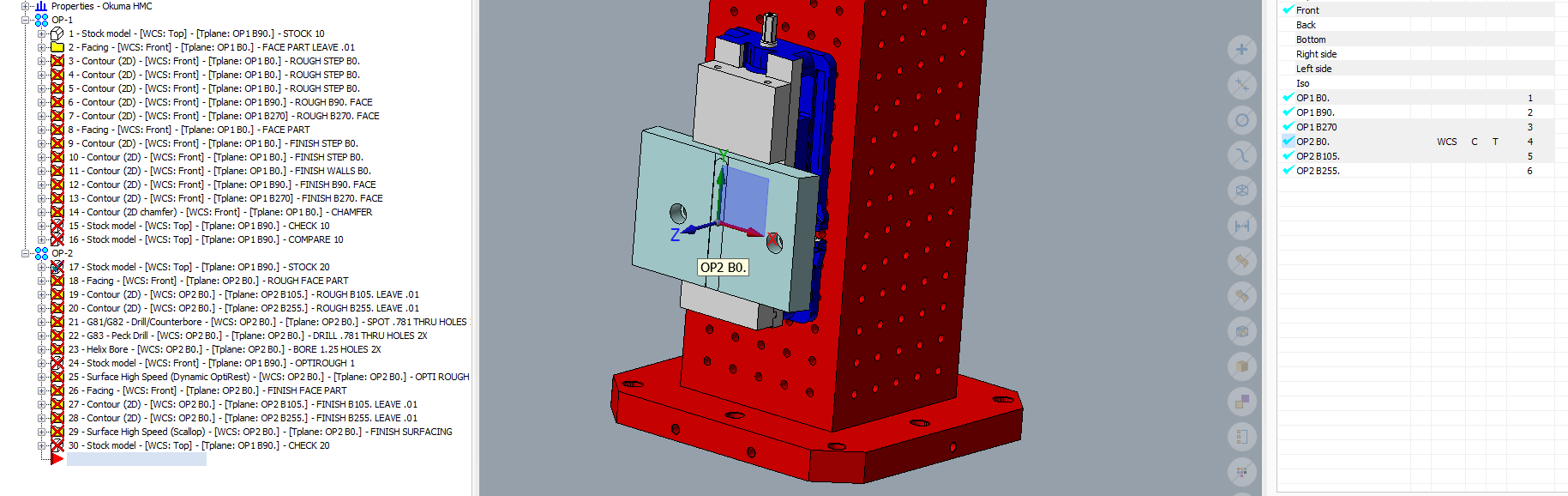
How are you setting up your tombstone programs? I want to see if anyone has alternatives to what I am doing. Currently, I have a template with the tombstone and vices loaded in as well as a few WCS already setup. I import a part model, position the part in the vise as I see fit, and program from that point. I break the tool paths down to operations as I'm usually only running a hand full of parts so it's not a big deal. A stock model is created for each op and I post each operation out on its own. I have a G10 setup for the post and get my numbers straight from Mastercam. It works okay but I wanted to see if others are miles ahead of me and what they are doing.
Thanks for reading into this
PS, the attached picture is an incomplete program so there are a few inconsistencies.
-
22 hours ago, So not a Guru said:
About the only time I use the alt key is to type ascii characters
 22 hours ago, JParis said:
Nope, left ring finger on the ESC button on my Space navigator...I drive the interface 90% via RMB..very little extra mouse movement and quick.....as I have used this setup since the inception of , I know the menu and where things are located and can just move my cursor and be where I want....
Rarely if ever, do I use the ALT key
I stand corrected.
-
This post is getting sooooo long. I don't think anyone else has mentioned this but a new gem I have started using is setting up your quick access tool bar. Most power users (that I have seen) keep their left hand near the alt key on the left of the keyboard for easy access to a list of functions, most notably top view (alt+1). With the quick access ribbon, you can add a few quick functions by tapping alt (not alt+) then hitting a number key.
-
Agreed.

-
Thanks. I'm glad to be around again Ron.
-
Edit: so, apparently I don't know how to attach files.
 If someone will help me with that, I'll share the .set file.
I haven't been on in a long time. Moved to a new state, new company, all that jazz. Anyway, I just finished work on a handy little .SET style setup sheet. I was previously using the active setup sheets but they tended to be a little more than I need for most jobs. For the most part, this is a rough draft but it's a good start. I have Cimco setup so that it will print two columns with margins at 1in and line count at 80. Below is an example. The .SET contains a buffer to avoid the reposting of duplicate tools and it will output tool holder names only if you use them (if <> "Default Holder"). The only point of me sharing this is to give back to you guys because you guys taught me how. Any questions or suggestions are welcome. Even just writing this post has given me a few new ideas. Thanks.
BRENDELL MANUFACTURING MILL TOOL LIST ------------------------------------------------------ ~~~~~~~~~~~~~~~~~~~~~~~~~~~~~~~~~~~~~~~~~~~~~~~~~~~~~~ N 1 G81 SPOT DRILL .39 DIA HOLE DEPTH = -0.190 TIME = 7 S ------------------customer info---------------------- ------------------------------------------------------ Date = JAN. 31 2017 N 2 G73 SPOT DRILL 1.000 DIA HOLE Machine = MAZAK NEXUS_510C R 2 DEPTH = -0.250 TIME = 3 S ------------------------------------------------------ Tool List N 3 G83 DRILL .39 DIA HOLE --------- DEPTH = -2.167 TIME = 4M, 35 S ------------------------------------------------------ ------------------------------------------------------ N 4 G73 DRILL 1.002 DIA HOLE TO 63/64 DIA T1 = CM9 .551 DIA NINE9 SPOT DRILL 90 DEG DEPTH = -2.346 TIME = 2M, 26 S DIA=0.551 SOL=3.937 LOC=0.551 ------------------------------------------------------ ------------------------------------------------------ N 5 Misc_1 BORE 1.002 +.002/-.000 T2 = 25/64 DRILL DEPTH = -2.030 TIME = 1M, 26 S DIA=0.391 SOL=2.297 LOC=1.125 ------------------------------------------------------ T3 = 63/64 DRILL DIA=0.984 SOL=3.000 LOC=2.000 ------------------------------------------------------ T4 = 1.002 BORE TOOL DIA=1.003 SOL=5.551 LOC=0.500 ====================================================== (4 TOOLS):(5 OPERATIONS) ------------------------------------------------------ Max_X = +15.808 Min_X = -14.558 Max_Y = -0.097 Min_Y = -0.603 Max_Z = +3.000 Min_Z = -2.346 Cycle Time = 9M, 8 S-
4
-
-
-
I wanted to get an idea of what others are doing to manage their data. Between the .mcx files, the .nc file, tool libraries, solids and post files, things get a little crazy. What have you found that works well. I am looking at a few software options and even visiting the idea of putting something together my self. Solidworks pdm works great, but the cost is a little to much for the outcome. I have seen people put together software using filemaker pro but i'm not sure if that is too involved for me right now. Anything you guys have found that is simple and low cost?
Arcs/Tool change output lathe
in Post Processor Development Forum
Posted
Huh, I'm kinda stumped. It's hard to tell what is going on with this post because they are constantly overwriting variables manually. This is a little more in depth than I am really able to tackle on my free time right now. I'm going to follow this post and maybe in a few weeks I can dig into it a little more. If you can create a zip2go file then pm me the file I can try and debug on my end later.