


pullo
-
Posts
464 -
Joined
-
Last visited
-
Days Won
2
Content Type
Profiles
Forums
Downloads
Store
eMastercam Wiki
Blogs
Gallery
Events
Posts posted by pullo
-
-
you mean like : Toolplane Origin : X0. Y181.93 Z-4.953 ?
if prmcode$ = 15131 , X_orig = rpar(sparameter$,1) # TOOLPLANE ORIGIN
if prmcode$ = 15132 , Y_orig = rpar(sparameter$,1) # TOOLPLANE ORIGIN
if prmcode$ = 15133 , Z_orig = rpar(sparameter$,1) # TOOLPLANE ORIGIN
Gracjan
-
 1
1
-
-
copy , paste ,:)
-
 1
1
-
-
Cimco will not do 5ax -code .....but for what you are doing (aligning) 3ax is enough?
Gracjan
-
I believe it was V3 that had the .ge3 for it's "3d files" . Drilling was done in a separate program and the files were .ge2 . The reason why drilling and the rest were separate was to overcome the 640 KB max memory of the PC . Then we started to load mouse drivers above the 640 Kilo limit etc. and eventually were able to use the whole mega memory.... Could be V2 , it was 1990 or something
.gif ":)")
Gracjan
-
this was just asked and answered a few days ago, a bit more specific than this
Gracjan
-
I was a little confused by the "Tool icon ". It's called the "Toolpath tab" .
Gracjan
-
this behavior has been around since 2017 ....
For one , you are technically incorrect, because even if your toolpath menu disappears , you can still access toolpaths from the Operation area via your RMB button.
There is a way to bring back the toolpaths
Open a new machine group that is not Mill. Now activate the miling machine group and presto , you have your dahling milling toopaths back
You can now delete the unnecessary machine group. I dunno if this works if you have no other machining groups available on your sim.....
Gracjan
-
1
-
-
just as I thought . it's the sharp ridges that might cause pain here. I brought it in as surfaces and just a tweak of tolerance from my usual 0.025 mm to 0.05mm made it into a proper solid . So that was easy. Using a larger tolerance for stitching does not make the part any less precise , it is just a precision to use for Mastercam to see it as a solid.
No physical editing was needed here.

-
yes there is . thing is , even if I tell you it still won't solve your problem.
You get a sheet because the solid is not airtight and the missing seam has to be found.
Here is a little experiment to show you this.
1. draw a solid cube .
2. from model prep using remove face , remove one face. You now end up with a sheet solid.
3. Now create a flat or ruled surface to make up for the missing "pane".
4 . NOW USING SOLIDS: FROM SURFACES choose the sheet and the one surface to create a solid and choose "Blank " as to what to do with the debris , so it does not confuse you.
Presto , you have healed your Sheet back into a solid .
The thing is YOU KNEW WHAT THE PROBLEM WAS with the cube sheet... When you get a part with a thousand surfaces , we have no analytic tool in Mcam other than "Create curves on open edges to guide you as to where the problematic crevasse is ( it usually is that) .
So what are the options ?
1. Using "Create curves on open edges " try to create a solid from what you have if you want to keep it in the Mcam realm.
2. Solve your problem outside of Mcam . Solidworks has a system for repairing solids. ZW3d is a very inexpensive system that will patch things up and then there is specialist stuff like Caddoctor , Cadfix and one more but I never remember it's name....
Gracjan
-
-
And then of course we have the "Only display associative geometry" button in the op manager.....
Gracjan
-
1
-
-
Matsrecam 2020
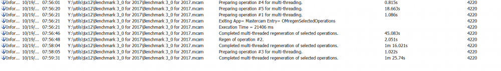
3 minutes 47 sec Metric 1
Very good news from 2020 testing . Calc times have improved by 5% compared to 2019 . My initial result looked like 2020 might be slower , but I was just sloppy.
All other Mastercam sessions must be killed off as they seem to influence the end result.
Compared to 2018 that makes it a whopping 26% improvement in calc times .
Gracjan
-
1
-
-
since its 1500 of these it is worthwhile to invest time in thought here as once you slash the time its 1500 times that . could you send a file before and after ? My line of thought here would be to investigate whether its possible to create the needed geometry using surfaces. Also shading surfs might make proofing the design easier on the eyes.
Gracjan
-
The last time this was around , we had to update the Nvidia driver of the PC ...
Gracjan
-
That will be difficult . ..... You could make a master copy and make the pc replace the working file with the master file every morning with task scheduler. However if Mastercam is already open , that won't work....
or start mastercam with a batch file , where the first command would be to copy the master to the working file ....
Gracjan
-
 1
1
-
-
I had an hour session with it a week ago and the results were so weird ( read unusable) that I ditched the whole idea . I went back to my old style , surface contour and old school shallow set at 10 degrees , with the size of the tool in shallow 0.3 mm larger that in reality.
Gracjan
-
1
-
-
Some tend to think that Metric 2 tells more about parallel processing. I was happy with Metric 1 as we had one clear number . Now basically one has to inform if he is a 1 or 2
believer ....
Gracjan
-
Just a recap of Benchmark 3.0 . We have spontaneously created a new, parallel metric here (Metric 2) , whereby to get the total time we subtract the first time from the last time.
The original metric was adding all the times together (Metric 1) .
Orvie seems to have the best machine , but we have yet to wait for his 2019 results to come in and then there is the overclocking .... The best comes at a price , the Intel I9 7980XE
is a whopping 2100 euros. I would think that he's Metric 1 would be in the range of 3.5 minutes and Metric 2 3.1 minutes , so a top machine will be nearing the 3 minute range
I seem to have the second place here , but I have overclocked the memory and the processor and added water cooling .My processor was only 300 euros . Metric 1 is 3minutes 57sec and Metric 2 is 3min 37 sec
Gracjan
-
1
-
-
Ok , that was a direct hit on the nail . "We stopped using MC4SW and got the full version".
Gracjan
-
1
-
-
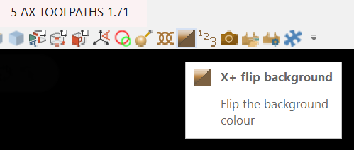
I use a classic black backdrop , but if I ever would have wanted to change instantly to a gradient I could do it with the "X+ flip background " command.
However I have yet to use it
. But the option is out there.
Gracjan
-
also it would not hurt if you specified who's post you are using.
Gracjan
-
The DMU 50 until now and by until now I define as 2017 can turn B+110 - B-5 . The new generation ( it's coming over to my neighbors in a month) will turn more on the negative side I'm thinking B-91? . Almost every 5ax post has B limits defined as variables , so you should look for those limits somewhere in the post if you have this newest generation and change them.
-
For example I have never had this color issue happen , like never , so I must be doing something which does not induce a crash..... The lack of crashing is also a good lead .
Gracjan
-
This is an issue , which like Mcam adding planes called "Group Machine Group - 1-Mill" is very hard to pin down . I would suggest everybody tries to jot down (obviously from memory) the preceding steps . Then we have to get them into one thread and I'm sure pretty soon we'll see patterns emerging and then we'll have something to present to CNC .
Otherwise we'll be stuck with these "randomly " occurring issues forever. Colin , U up for the infra here ?
Gracjan


Force WCS coordinates?
in Post Processor Development Forum
Posted
A toolplane is defined by : A ) it's origin and B:)the direction the axes are pointing . I was asked only where would one gets the WCS coordinates from and I think I answered this question. JLW , the origin of a WCS can always be defined by the X,YZ shift in the World coordinates. To define the way the axes are pointing , you need a 9 digit matrix .
Here is info provided by Mcam for a random Toolplane :
View No. : 25
Work Offset : Off
Origin (world) : X0. Y0. Z-105.25
Origin (view) : X0. Y0. Z105.25
Matrix : X0. Y-1. Z0.
: X-1. Y0. Z0.
: X0. Y0. Z-1.
"So, how does this work if your Z vector is not = top/top/top?" -
my answer to this would be "it works". You would have to give me more info on what you mean by your question.
Gracjan