


Kampfzentrum
-
Posts
125 -
Joined
-
Last visited
Content Type
Profiles
Forums
Downloads
Store
eMastercam Wiki
Blogs
Gallery
Events
Posts posted by Kampfzentrum
-
-
Thanks in advance for any who took the time to read/comment on this.
The company I am with had Mastercam back in the day and had an old post for a Toshiba HMC. Asked the reseller to modify and they wanted $500. I am on a departmental budget and am currently switching from CamWorks to Mastercam and I'm blowing my margins. The post I have works but outputs certain codes in areas that it shouldn't and is erroring out the machine. See the code below:
O0000 (1520875B)
(OVERALL MAX - Z6.25)
(OVERALL MIN - Z-1.6694)
N100 G00 G17 G40 G80 G90
N110 G53
N120 G91 G28 Z0.
N130 (MACHINE PAD B, 4.000 STEPOVER, WEAR COMP ACTIVE)
N140 (COMPENSATION TYPE - WEAR COMP)
N150 T2
N160 M06 (8.000 INGERSOLL GOLD-MAX4 FACE MILL)
N170 (MAX - Z4.)
N180 (MIN - Z0.)
N190 G57 H901
N200 G00 G17 G90 X-151. Y5.5
N210 G173 W0.
N220 G43 H2 Z4.
N230 M01 <<< WANT IT REMOVED.
N240 S360 M03
N250 T3 <<< WHY IS IT CALLING UP A TOOL RIGHT NOW??? NEED IT REMOVED.
N260 Z0.
N270 G94 G01 G41 D2 Y1.5 F37.
N280 Y1.3899
N290 X0.
N300 G40 X5.
N310 G00 Z4.
N320 X-155. Y5.5N330 Z0.
N340 G01 G41 D2 Y1.5
N350 Y-2.6101
N360 X0.
N370 G40 X5.
N380 G00 Z4.
N390 M05
N400 G173 W0. <<< NEED IT REMOVED.
N410 G91 G28 Z0. <<< NEED IT REMOVED.
N420 G53 <<< NEED IT REMOVED.
N430 M01 -
On 3/10/2019 at 11:09 AM, Colin Gilchrist said:
I'm happy to help when I can Justin. Glad it is working for you.
Wanted to explore this because I am experiencing the same issue. Now, I could make the suggested post modification above, but we have a shop with a number of various machine tools that all require D/H offsets to match the tool. So, in keeping things uniform, is there an internal parameter in the Makino controller that will enable it to accept D/H offsets with the same number as the tool?
Just curious.
-
7 minutes ago, So not a Guru said:
Migration Wizard is available at least back to 2017. File>Convert>Migration Wizard.
You're probably going to have to migrate it in steps through each version.
I actually got it. I double-clicked on each one and had to manually re-map each file to each other since the last time it was used it was in ...SharedMastercam2017. So I re-linked them all together in the newer folder and they successfully updated.
-
 1
1
-
-
I've recently come across an old post for a machine that my company let sit idle but now we are looking to use. We are now using Mastercam 2023 and the last time this post was run was X9. I have the control file, machine definition file, and .pst file. When I dropped them in their respective areas in the Shared Documents folder (i.e. CNC Machines and Post folders) and opened up Mastercam to import them in, the files were not seen by Mastercam. I believe this is because the files have not been updated as we updated with Mastercam. Is there a way that I can get these files updated so I can run the post - outside of consulting my Mastercam Reseller.
UPDATE: I am aware of the Migration Wizard, but it only goes so far back as Mastercam 2020.
Thanks.
-
55 minutes ago, crazy^millman said:
Just extended the chain our far enough to allow the tool to start on the outside and it did exactly what you wanted. Easy peasy. Use inside as the control and done.
Remember the chain is just a suggestion and the stock is the real boundary.
I did change the process to not peel mill the section, but dynamic the section. If you want the peel method back then just move the two chains back to the original place they were.
Thank you for sharing the file. This will be another subject of teaching when I go onsite and teach the Advance programming methods to customers.

Yes...
I was in the habit of creating about .100 of clearance outside of the part for security that everything was getting machined. Looks like I need to eliminate that.
Much thanks for giving me the nudge in that direction. You get an ice cold Coors Light. What?! No NASCAR xxxx? How about a New Glarus Moon Man? No Coast Pale Ale is where it's at homie! Much thanks again!
-
10 minutes ago, crazy^millman said:
Only way I can think of would be to mirror the toolpath using Transform. Your logic makes perfect sense, but without a file to play along with at home so the those who like to tinker can tinker with it can try things that is all I got for you.

Play away!
An imaginary beer will be bought for you upon solving. I couldn't get the Transform to work. It just wanted to recreate the same starting point.
-
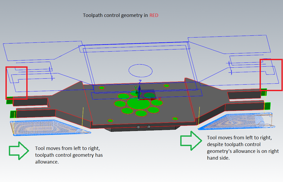
I've searched the big bad Internet all over and got multiple leads but no answer. The question is simple. How to change a Dynamic toolpath machining from left to right to right to left. Please don't say Toolpath Transform via Mirror unless you know it actually works. I played with it for a while and still got this same starting path. Now here's the oddity No. 1: Mastercam gives you the option to create an "Approximate start point" but I've NEVER seen this work inside of Mastercam - not even sure why it exists. Oddity No. 2: I've specifically allowed - through the toolpath control geometry - Mastercam a poopload of area to put the tool down in, but nope! It wants to put it down into the small itty-bitty area that it has on the opposite side.
People will ask, women will whisper, "Why does he need the toolpath to go right to left (on the righthand machining operation)? Because this plate will get thinner as it machines and I'd rather machine towards the workholding (vise) than away where rigidity will weaken.
So, simple question, hopefully simple answer: How do I change the direction of the righthand toolpath to run right to left. See image if unclear.

-
I'm not sure if there is documentation on how setup sheets are organized, but I pretty much figured it out by tinkering around.
My biggest issue is trying to understand how to space data fields (when the .rpx file is called up). Or how to prevent them from creating a new page (i.e. parallel to a page break). Just wondering if anyone knows if there is some instructional literature out there or if they know what I'm talking about. HELP!
-
55 minutes ago, crazy^millman said:
No not you many have complained about this enhancement and have asked that the more user friendly method of contrast used by a majority of software companies be added back to the software.
I find it completely annoying, I don't know how anyone could not complain about it. But I guess I'll have to wait...
-
Call me crazy, but the icons (parameters, tool, geometry, and toolpath) under each operation looked like they've been lightened to the point where they are not selected. Is there any way to bolden these colors? It honestly bothers me.
Or is it just me?
-
DISREGARD. Solved my own problem.
-
I really don't have much experience with 3D toolpaths, so I need a jog. I'm machining out a relief in a part and I'm not understanding why the tool is avoiding certain areas. I'm using a .500 ball endmill and the roughing program I'm using is not only not going into the corners full (purple boxes), but is also leaving a big swathe area that has me baffled. I attached the file, could someone lend me some advice as to what is going on here?
Also, what would be a good finishing operation?
-
1 hour ago, JParis said:
Several Ramp options here
MUCH THANKS! I've completely missed that PLUNGE option. That's what I needed!
-
1
-
-
37 minutes ago, savagkd said:
Try a Ramp. It will not plunge at the ends, but may get you where you need to be.
The endmill type I'm using is just not liking that downward feed.
2 minutes ago, #Rekd™ said:If you use Pocket, create a point where you want to plunge. Chain the pocket first then add a point where you want to plunge. I usually use contour ramp for slots though.
See this video.
I didn't like using a Pocket operation for something so small. Instead, I offset the same linear lines .0001 off of center and connected them (creating a very small rectangle). I then ran a contour off of that geometry (no comp). It kind of worked...
-
I have a question about the simple 2D contour...
I create a simple linear line, 4" long, and running in Y. Lets say I want to create a slot (in this case .25 wide), I create a 2D contour and select the geometry. Now, let's say I want the tool to feed down, run along the geometry I created (no compensation), and instead of retracting and returning back to the start point I want it to feed down and mill back to the original start position. From there it would continue to mill, feed down, mill, feed down, etc. until it reaches the specified depth.
I am unable to figure out how to do this using a simple 2D contour, is there another way?
Thanks for the help.
-
Greetings dudes! So I've been programming for a number of years now (15 year journeyman beforehand) and I am curious enough to now step into the world of post code (i.e. the code inside of the .pst file). I'm doing something as simple as modifying the program headers but have figured out that it would be best to start learning about this code before cracking it manually. So, before I start randomly popping off questions, let's start simple:
What is the name of this code?
Is there a key that defines what these codewords do (e.g. "spathnc", "smcname", etc.)
Is there any instructional media that could help me grab up on this quicker?
Let's start here. Much thanks for your time.
-
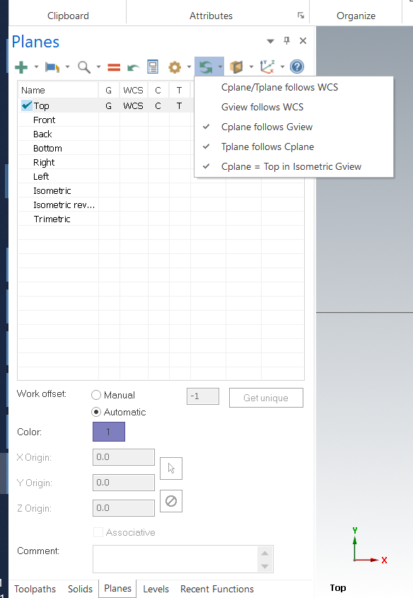
1 minute ago, #Rekd™ said:
Setting in the Planes manager.

Much thanks! Never dealt with this before! Thanks for your time!
-
1
-
-
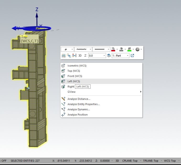
Running 2021 for the first time and I'm a bit confused due to the plane/view orientation. Normally, if I selected different planes to view from, the C/T plane would change with it. For instance, say I wanted to rotate a part. If I started in the top view, I could rotate that part looking from the top view. But - while still in the rotate command - I could change views (say left plane) and the plane of rotation would change with it. In the image I attached, I am in the left view, but my plane of rotation is still the top - as you can see my C/T planes are staying in the top plane. How can I change the plane to the view I'm in? That's just the way I've ever done it.
-
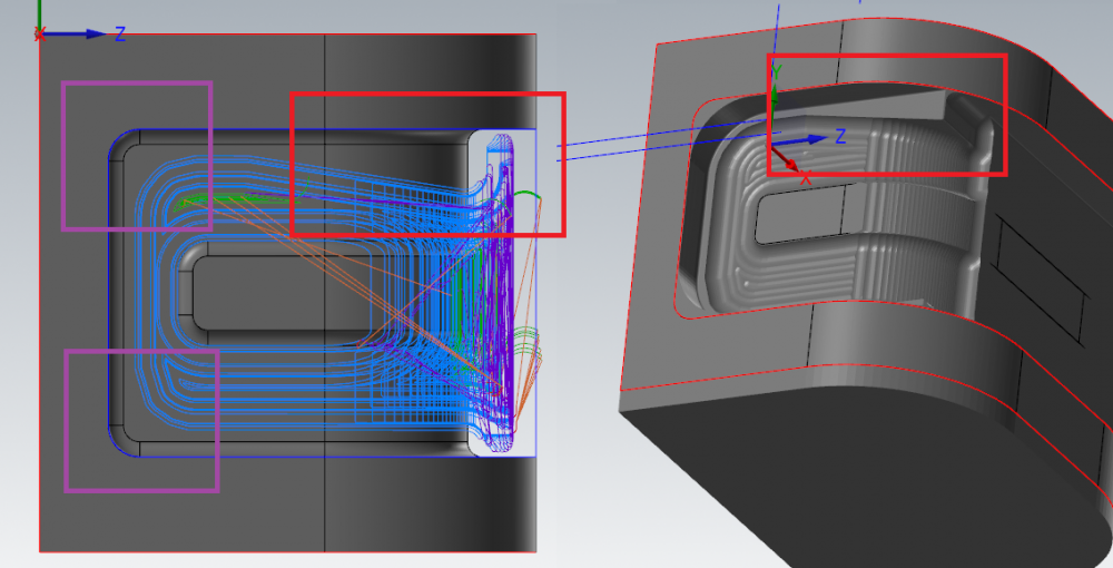
I'm cutting a small draft on a diameter with a .250 ball endmill using a waterline tool path. The CAD is a solid and the draft is uniform (i.e. no "cracks" in the model) yet when I generate the toolpath I get these constant retracts that just skip over these small tracts of area. What is doing this and how can I reduce this? I've played with every setting imaginable and it only seems to get worse.
Help? Much thanks in advance.
-
1 minute ago, JParis said:
Click on the link in the post right above yours
They're right there
Gah! I was looking for a tab! It's downloading! Thanks.
-
Bump!
I could use a tool library with these SAE guys in there. Appears this thread hasn't been rattled in awhile so I figure that people seem to know where to get them. I'm completely out of leads.
Help!
-
OMG, I found it... Good Lord. Yes, apparently I've been in the dark for awhile now!
-
 1
1
-
-
22 minutes ago, JParis said:
Surface Rough Contour is still in 2020....
It may not be on the ribbon bar but try right clicking in the OP Manager >> Mill Toolpaths >> Surface Rough...you'll find it there
I think I'm going to sound really stupid, but what is this "OP Manager"? I normally select all my toolpaths from the 2D/3D/Multiaxis sections on the Toolpaths ribbon. Is there something I'm missing? Don't tell me there's a whole new side to Mastercam I've never seen!!!
-
So I'm going through some of the older programs here at work and stumbled upon an old file made from - I assume - X8 and there is an operation called "Surface Rough Contour". Opening it up, it had to older style tab interface unlike 2020 and found that the contour wasn't defined by a line/chain but the model. It basically works like a Waterline and cut around the geometry of the part - minus the horizontal surfaces.
I looked all over for a similar operation in 2020 but could find nothing in the 2D toolpaths that could parallel it. Is there something that I am missing? Is there an equal to this that I don't know about?


Need assistance with old post HELP PLEASE!!!
in Post Processor Development Forum
Posted
All of this would be in the .pst file?