


KORLOY
-
Posts
37 -
Joined
-
Last visited
Content Type
Profiles
Forums
Downloads
Store
eMastercam Wiki
Blogs
Gallery
Events
Posts posted by KORLOY
-
-
Hi guys!
I have a problem while posting programs for our 5 axis Okuma 5000V. Sometimes, when I post couple operations of the same tool, in operation change it post with A90 (POSITIVE direction - table rotates from the operator) which is not comfortable and safe to work. It post like this even when I'm forcing it thru misc values (mi10). Same thing happens when I'm transforming operation (by rotation) - in some angles it can post positive. But it never happens in the beginning of the program and with force tool change ON in operations. My vector section in the post looks like this:
What do think, why it sometimes rotate positive?
Thank you for your thoughts!
-
On 8/2/2020 at 4:13 AM, Greg Williams said:
That one is not connected to the machine and control def. You can change the settings around to run a BC output, Are you running G169 and CALL OO88 from that post? If yes you may need to do some work in there as well if you are running a 3+2 safe approach for 5 axis
N1 T6 ( EMUGE 12250A TOOL - 6 )
M6
G15 H1
G0 G90 A-63.1049 C19.1142 S4000 M3
CALL OO88 PX=0. PY=0. PZ=0. PC=19.1142 PA=-63.1049 PH=1 PP=51
G0 X3.5817 Y28.2171
G56 HA Z101.0398
G15 H1
M510 (CAS OFF)
G169 HA
G1 X-30.3024 Y98.3763 Z20.5411 A-63.1049 C19.1142 F15000.
G131 J2 E=0.05 D=0.025 I0 F25000. (SUPER NURBS ROUGHING)
M8Hi guys!
Yes I'm running CALL OO88 from the post and it works fine for 3+2 applications (there is no need for G169/TCPC at the moment). And I'm wondering what changes to do in the post to make it work for the new machine. I have open post from HAAS UMC 750 - I will try to copy some logic from that post. Is there enough to change post in the vector section or I have to change something in the machine definition manager?
Thank You for the answers guys!
Best regards!
-
Hello guys!
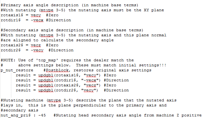
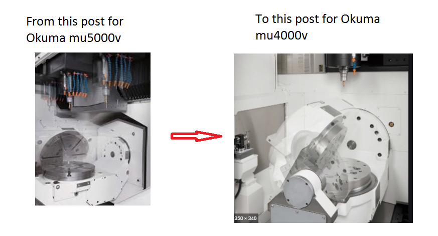
We bought new Okuma mu4000v and I need to make some changes in my postprocessor. I have post for our mu5000v which works fine and I want to set up this post for new machine. Main differences of those machines is trunnion position according to XY axis. I'm adding some photos to make it clear.
Is there enough to change only vector section of the post (added the photo) or is there something else?
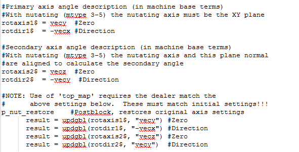
For MU5000v vector section in the post looks like this:
Thank you for the answers guys!!
-
Hello guys!
I need the recommendations how to set up PC and MC for proper work. I just don't have no more patience with Mastercam calculation times, it's just too long. Even small and not really complex parts/surfaces/stock model creation takes lot of time for calculation. The PC itself is a BOMB:
Intel Xeon E5-2667v3, 8x3.2GHz 20MB Cache 3.6 GHz Turbo, 135W, Hyper Threading
32GB RAM
NVidia Quadro K4200, 4GB
1.2 TB SSD Intel S3500
500GB HDD
Windows 10 pro
Hyper threading and all cores are enabled in BIOS
Memory buffering is set to 85% in MC system:
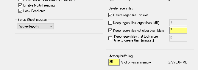
During calculation Task manager shows that ONLY ONE CORE of CPU IS WORKING at HIGHER INTENSITY while average load on the system is only 5%. Why is that and how to activate other seven(+8 virtual) CORES of CPU?
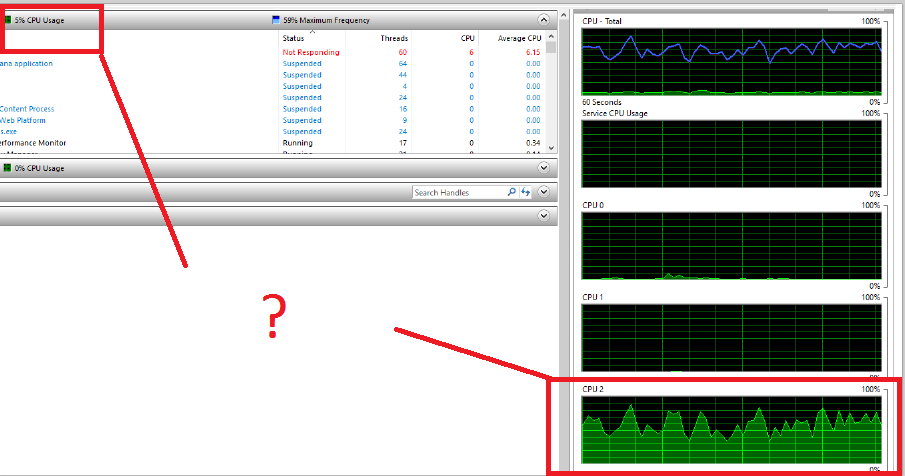
Where the problem can be, what other settings I need to change to get best performance? I am wondering what PC is necessary for really big and complex parts to program with Mastercam?
Waiting for your thoughts and answers!
Kind Regards
-
remove this topic
-
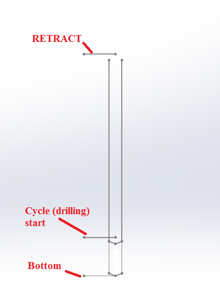
Hello guys,
I need some advice how to solve this. The situation is following: After deep hole drilling with long carbide TSC drill I need to finish my hole with longer HSS drill (on intersecting holes and etc.). When I use standart G83 Cycle it start's on R plane which is retract point, what I need is to start first peck deep in a hole ant retract to R plane (for normal chip removal). How did you guys solved this? Maybe somebody created custom cycle on your control? Now I'm solving this with transforming 3D contour operation (getting the bunch of coordinates for drilling). The photo is for better understanding:
Thank you for any advises guys!
-
Thank you a lot!!!! worked!!!
By the way I commented---> #!op_id$ before this check, you can see it in the photo I attached if someone will need this in the future
.gif ":)")
-
22 hours ago, Colin Gilchrist said:
But for this to work, it also depends on where in the Post the 'op_id$' variable is updated. Some Posts have '!op_id$' at the end of 'ptlchg_1002'. So what I do is comment out, or remove that code, and add '!op_id$' to the end of 'psof$', 'ptlchg$', and 'ptlchg0$', so the 'op_id$ <> prv_op_id$' check will always work...
Note: ignore the single quote marks when using the variables...
Thank you Jeff, Colin and jlw™ . I made everything like you guys said (made a check - if op_id$ <> prv_op_id$, and updated "!op_id$")

but it causing an error

Where the problem is?
-
I tried your method "JLW" but it didnt worked, it's still posting N on EVERY RETRACT
Program looks like this :


As you can see I manage to get correct N on the Start at the program and at ptlchg$ (#Tool change), but at ptlchg0$ (tool number repeats) It's not working like I prefer.
Here is a post segment:

By the way, why pspindchng is working great? It changes only ONE time with retract to second block.
I'm so close to get result that I want
 , than my N will perfectly match X+ setup sheet!
Thank you!
-
Hi guys and "So not a Guru"!
I have absolutely same problem - I can't solve my op_num output on every retract. So how you solve the problem? I played with
If op_num <> prv_op_num & omitseq$ = 1 & tseqno > 0, pdosomething.
like Colin said, but didn't worked for me.
So,
n$=op_num
pbld, n$*, e$added in the ptlchg0$ postblock is causing op_num output on every retract, what logic I need to add in this postblock to get correct op_num output)??
Thanks for the answers!
-
Hi guys!
I have the similar problem like Brandon, I'm trying to setup the generic SODICK MARK_30 4X WIRE.PST for our EDM WIRE machine wire LN1W control. At the moment we are using HeartNC programming software and it post correct HEADER at the start of the program I mean:
( = ON OFF IP HRP MAO SV V SF C PIK CTRL WK WT WS WP);
C000 = 010 016 2215 000 360 040 8 0015 0 000 0000 025 160 150 050;
C001 = 012 016 2215 000 364 025 8 0015 0 000 0000 025 160 150 060;
C002 = 003 018 2215 000 750 045 8 6020 0 000 0000 025 160 150 012;I need the same logic at the MasterCam Post. I have the HeartNC post but the I have no idea how to tie up them together, there is fragment from HeartNC post:
# C*** H***
IF(WVV_NC_energy_mode <> WCV_NC_ENG_NOT)
LET cnt 1
# /* 加工条件ヘッダー部タイトル */ /* Add by I.Hara '98.03.16 */
LET rtn (FWRITE(outfile, ("( = ON OFF IP HRP MAO SV V SF C PIK CTRL WK WT WS WP);")))
LOOP
EXIT_IF(cnt = WVV_PP_c_buf_pos)
LET code (GETA("WVS_PP_c_buf", cnt, 0))
LET code (GETNUM(code))W_get_rec[WVS_MSPEC_DIR + WVS_ECOND_NAME, code]
LET codel (STRDLM(WVV_PP_return_value, "=", 2))
# /* 加工条件桁数によりブランク数が異なる */ /* Add by I.Hara '98.03.06 */
IF(WVV_MS_CCOND_FIG = 3)
LET rtn (FWRITE(outfile, ("C" + code + " = " + codel + ";")))
ELSE_IF(WVV_MS_CCOND_FIG = 4)
LET rtn (FWRITE(outfile, ("C" + code + " = " + codel + ";")))
ELSE
LET rtn (FWRITE(outfile, ("C" + code + "=" + codel + ";")))
END_IF
LET cnt (cnt + 1)
END_LOOP
END_IF
Any ideas how to make post like this? I know that the company http://www.shopwareinc.com/ are working with setups for Sodick edm wire machines, maybe someone are using database from shopwareinc ?
Thank you for any answers!
-
Hello post gurus!
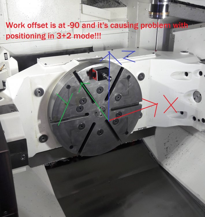
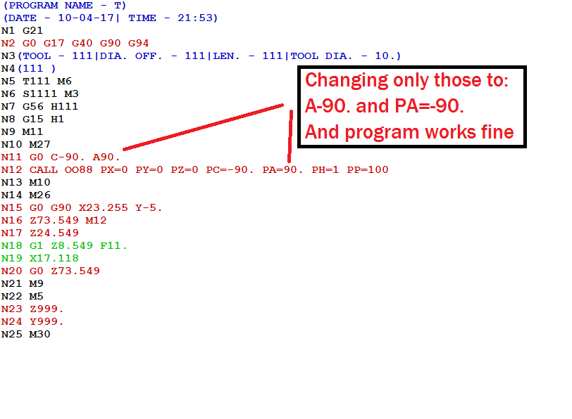
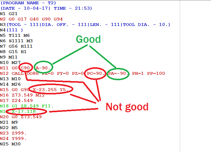
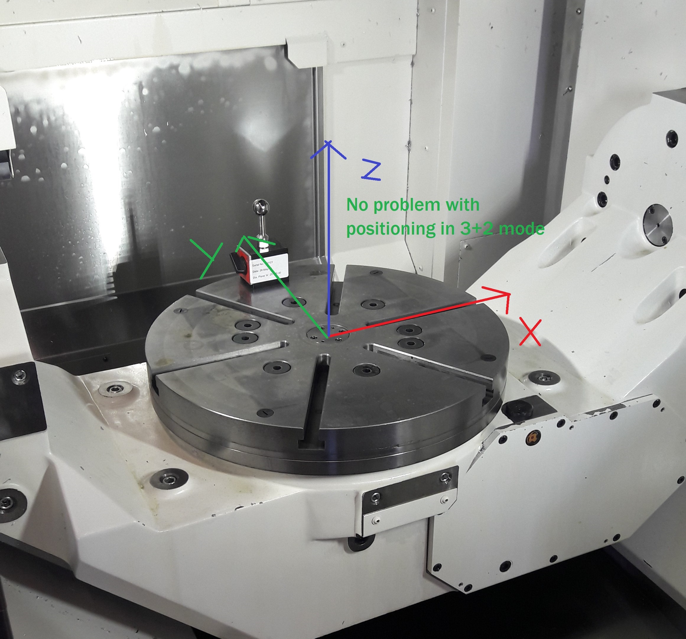
I have a problem with my custom 5 axis post for 5axis table - table vertical Okuma in 3+2 mode. There is no problems when table is positioned (work zero) at A0, but when my table is rotated at -90 (and the work zero is setted up) the problem in angle positioning occurs. What post changes I have to made to solve it? I will be thankful you for any answers!!

-
Thank you Huskermcdooge!!! That worked!!!
-
Hi guys!
I am trying to set up old Okuma 5X post for a newer control and have some questions after some multiaxis programing using MCX6 (Those are mine first multiaxis attempts - sorry for a stupid questions)
So, I have a several questions/problems:
1. After posting multiaxis toolpaths the coordinates differs from one in the Backplot - where can be the problem with that?
2. The inverse time feedrate for 5 axis is not turning on using Control Definition Manager - where can be the problem with that?
3. In older version control there was no TCP control. What main changes I have to do in post (instead of adding TCP activation godes), to make my multiaxis toolpaths work? - maybe there are some hidden issues which I don't know about?
I will be thankful for any answers!
-
Hi guys!
I have been working with my customized 5 axis post for my Okuma (made one from Generic Haas VF-TR_Series 5X Mill), the 3+2 operations works fine but with one issue: I am changing the A axis positive meaning to negative - manually. I tried to set up my secondary axis output at miscellaneous values, setting it to post negative meaning but it also influence the C axis to positive! and other X and Y coordinates, which is not working for me.
Example without misc value set (that works with changing meanings manually):
Example with misc value set (does not working properly):
Maybe someone have any advises how to set up secondary axis properly to get negative axis output without changing other coordite values?
I will be thankful for any help!
-
WORKED!!! Thank you a lot, for a help!!!
I changed the formats of new variables (for wcs aswell) and the script now looks like this:
 Now I can only insert "poffsetrecalculation" where I need it.Thank you again for a step by step help! now I can go forward!!!
-
Hello guys!
The main problem is that my format section looks like this (Generic Haas VF Trunnion post):
fmt "C" 20 p_out #Primary output axis positionfmt "A" 20 s_out #Secondary output axis position
and changing the letters does NOT react my output at all!it reacts only in this place:# --------------------------------------------------------------------------# 5 Axis Rotary Settings# --------------------------------------------------------------------------#Assign axis addressstr_pri_axis : "C"str_sec_axis : "A"str_pri_axis : "" it works good but I need it only in one particular section!str_sec_axis : "" it works good but I need it only in one particular section!I'm thinking about adding some logic like thisstr_pri_axis : "C"str_sec_axis : "A"str_pri_axis_calc : ""str_sec_axis_calc : ""and another section with some logic like this (I want to show only logic, the syntax is wrong here, any advices to write it down correctly?)p_out_calc #C Angle without letterif RECALCULATION = one (will set this at one in the tables)[str_pri_axis = str_pri_axis_calc (str_pri_axis ( with the letter C are getting NO letter)p_out (Angle output without letter)]And after: pcan1, pbld, n$, "CALL 0088", *p_out_calc , *s_out_calc , "PH=1 PP=100", e$But I'm stucked with the syntax and place in the MP to insert that kind of logic, any advices will be helfpul!! Thank you! -
Thank you Ray for the advice! but there is some issues with this:
I cant change the parameters of an angles because, I need them without letters only at my offset recalculation line, in other turns I need letters of course!
I made some changes manually to show how I want program to look:
 That's the post part which need to be modificated (look at -->????):
Thank you for advices!!
-
Hi guys!
I'm looking for a possibility to break my angle parameters in the postprocessor (p_out, s_out) to get the output value of it only in degrees without the letters C or A.
For example: G0 C45. A54.736 <----- with the post line like this (pcan1, pbld, n$, *sg00,*p_out, *s_out, e$)G0 45. 54.736 <----- with the post line like this (??????????????)
There is no NCI output for them, I think they are calculated inside encrypted PSB file (correct me please), so how I can get does values as an output to my NC code, I need to put them to my angle recalculation macros line for 5x mill.
Thank you for any advices! -
Thank you civicegg! I found the answer according to your search criterias!
brk_mv_head : 1 #Break the 5 axis moves to remove gougeNow I set the value of 360degress like this : brk_max_ang : 360 #'brk_mv_head' maximum angle move, applied if chordalThe values may differ, I'm still in process building this post!
The path I get looks like this (photo) now! Thanks!
-
 1
1
-
-
Hello guys! I'm modificating my generic 5X post procesor for 3+2 milling on MCX6. It's a table table machine so I taked "GENERIC HAAS VF-TR_SERIES 5X MILL'' postprocessor to start with.
The problem I stucked at the moment is: my repositioning movement to other planes which needs to be machined goes by SMALL angles and steps until the angle I need. I tried some changes in Machine Definition Manager but any of them helped, maybe there is a other postprocessor issue?
I'm uploading the photo how it's look like (ignore the axis locking codes it's not modificated jet).

Thanks for any advices!
-
Thank you Colin for all the answers! I'm really appreciate it!

Secondary axis direction problem on 5x post
in Post Processor Development Forum
Posted
Thank you for the answer Colin! Solved it!