


Jespertech
-
Posts
119 -
Joined
-
Last visited
-
Days Won
1
Content Type
Profiles
Forums
Downloads
Store
eMastercam Wiki
Blogs
Gallery
Events
Posts posted by Jespertech
-
-
Seeing as how I get just about every technique that has helped me advance in my programming career from this forum; I figured I might be able to add a little something to help others just starting out.
Besides utilizing levels, groups/subgroups, and view sheets to help keep my approach organized and traceable I started making a copy of my solid and then changing the color of the finished feature as I work through the part.
Often times in more complex parts I'm not able to work simply from the top down and have to rough/ semi finish and then come back to finish before moving on to the next section.
By modifying the surface color it makes it very easy to see what has been done and what still needs to be finished at a glance.
My apologies if this was mentioned before in an older post and I just missed it.
Also, if anyone else has any techniques or tricks for tracking finished features that has helped them along the way please share.
I hope you all are gearing up for a great memorial day weekend


-
It's so wild to me that this topic was brought up this week; literally two days ago I had the typical know it all type criticize the way I approach my programming by utilizing the dynamic and the new toolpaths in Mastercam. I did my best to defend myself, making similar arguments that were brought up here. But perhaps because of my age or only having 5 years experience he was blinded to my rebuts.. So it feels really good to know that I'm not off base in my thinking. I'll probably even print this thread out and hang it on the wall for the next "back in my day" micromanaging meeting

-
1 hour ago, crazy^millman said:
Discipline in the process is the other thing I also teach to programmers. Label the levels, operations and other things. Doing one trick pony stuff okay maybe not needed, but my work is always gone over with a fine tooth comb and examined and picked apart. I haven't program a part for my eyes only in a long time. The habits I have developed are such that I know anything I do will be torn apart and checked and rechecked. Not a problem comes with what I do, but basics should never be ignored and things like workoffsets even for the one trick pony work should never be shortcut.
Well said, one of the best changes I made in my programming was utilizing the levels and groups/sub groups for organization. Being able to see my thought process and approach makes it so much easier for me to pick up where I left off in the event that I get pulled off of what I'm working on. Which unfortunately happens more than I care to admit.
-
23 minutes ago, crazy^millman said:
The Post writers fix for the Automatic crashing of 5 Axis machines. Look in your post for a switch that controls workoffset outputs. The default is one forced Work Offset to avoid this issues created by the unpredictable automatic work offset function added about 15 years ago. The training I give to all programmers is don't ever program any multi-axis project without setting your work offset through the plans manager.
Harrison's example is what I never do in Mastercam with regards to workoffset even for 3 Axis.
Here is how I am doing it in one project now.
this is exactly the direction I'm looking to go in, Thank you!
-
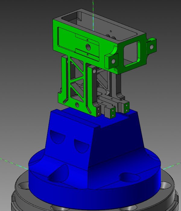
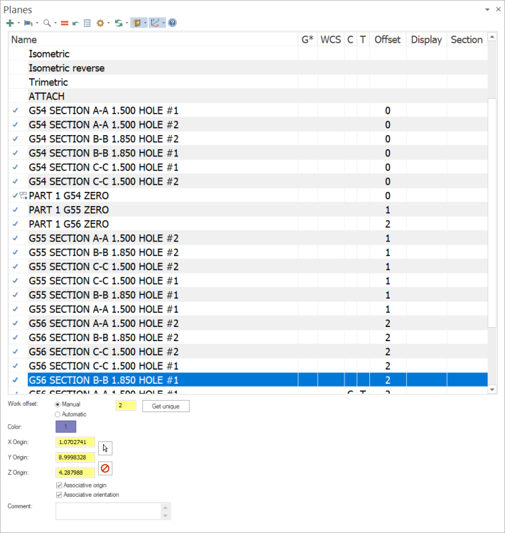
Well hey there gang,
I'm currently working on a part for our Haas 5-axis (a square with a dovetailed bottom) and I'd like to be able to have my work offset change for each plane (top=g54 front=g55 right=g56 left =g57). I tried setting my plane offsets to manual with top at 0 front=1 right=2 etc.. But something strange happens when I go to post the code. If I do the individual toolpaths they will have the altered work offsets but when I go to post them all at the same time it sets them all the same. This part is more for training than anything else. I'll add that it is the same tool facing each side, if that makes a difference.
If anyone has had this issue in the past and has figured out the proper way to get the results I'm looking for your input would be greatly appreciated.
Thank you.
-
On 5/9/2022 at 5:59 AM, gms1 said:
They tell me the size of the material they are going to buy. Then they buy something completely different forcing me to redo my program.
Glad to know I'm not the only one.
-
Man, I need to get whatever coffee you guys are drinking.. I'll be catching up on some
S.k. SINHA and then get back to this one

-
 2
2
-
-
2 minutes ago, Colin Gilchrist said:
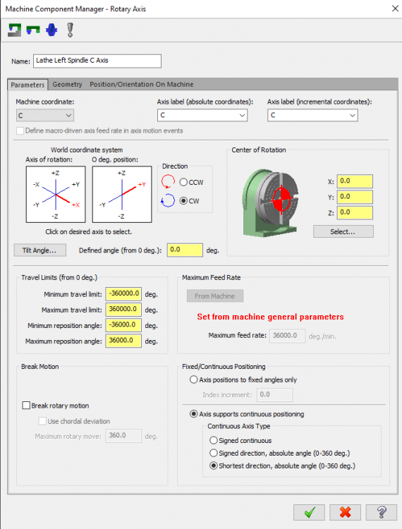
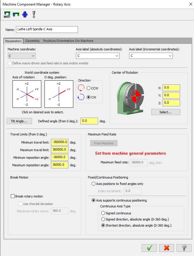
Try editing this > set it to '360000'.

c_limit      : 360000  #C-axis is limited to +/- this value
Ok, I'll give that a shot in the morning. Thank you!
-
 1
1
-
-
It is a NGC machine.
-
20 hours ago, crazy^millman said:
Change the Min and Max Travel to -360 and +360 and see what that gives you.
For reasons unknown to me even after changing those values it still presented a continuous revolution of the C-axis. I was pretty certain that would do the trick but no luck. I'm also using transform rotate in the program so that could have some influence as well. I'll keep these things in mind though and mess around more when things slow down a bit. Thank you for the input.
18 hours ago, Chally72 said:I know that in the case of things like the C axis of UMC's, when running a Next Gen Control, there are no longer any windup limits and you can safely change the control def min and max travel limits to a number of 9's in a row, (or go and edit your .pst if the axis limit values are stored there), to remove the unwind being added to your posted code. I think the limit still exists on the ST20's, however. You can give it a try and the worst that will happen is it'll reach the machine's max windup and then stop and throw an error when you hit degree 36,001.
Thanks Chally, I'm a bit of a novice when it comes to editing the .pst files but will hopefully be putting some hours into Collins youtube channel to learn more. Once I gain a little confidence there I'll surely be giving that a go.
-
just came across this.. gunna tinker a bit and see if its what I'm looking for.
-
9 minutes ago, altamontmfg said:
It's likely in the machine itself. What machine?
Haas ST-20Y
-
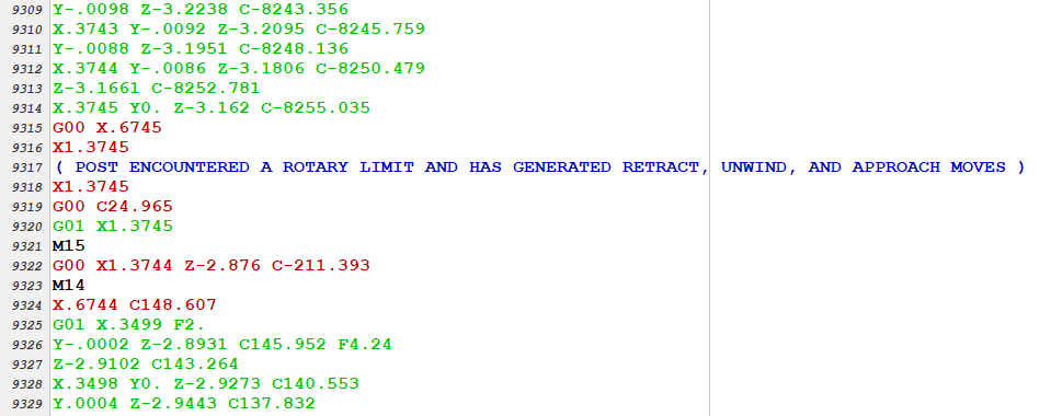
I'm working on a part that has slots machined around the body and due to the size of tool and depth of slot I'm taking multiple depth cuts to achieve a nice finish.
Which is working out very well, the only issue is that at one point in the code the C-axis reaches its limits as for as degrees rotated goes and creates an unwind.
Besides wasting a few seconds it really doesn't affect anything else... But man are those seconds keeping me up at night.
So I started looking through the machine definition and post control settings to see if there was a limit I could set that would keep my c-axis within a 360 degree spread.
I've had no luck, perhaps someone here has had a similar headache and could help a fella out before I lose it.
Thanks

-
In a case like this where there are blending issues I'll try to use a smaller tool to reduce the effect that Dylan pointed out above. It doesn't completely solve the issue but it does make enough of a difference to improve the toolpaths overall finish. I changed your tool from a 1/4" to a 3/16" lollipop and I think it made a noticeable difference on that particular corner. I know that may not be an option depending on what tools you have in stock but if so its worth a shot.
-
1
-
-
On 3/2/2022 at 2:06 PM, Hydrazine said:
I also tried to do it in mill-turn with a contour using plane rotation. This also makes the tool move instead of using the C-axis. I can change it from plane rotation to c-axis but, again, it only works if the tool is straight-on to the spindle centerline.
My apologies if this is a silly question but when you say it makes the tool move and not the c axis are you confirming that with the post or just going off the display when ran through backplot?
-
34 minutes ago, crazy^millman said:
Sorry, but this is the kind of teaching that is missing on so many of the sites. Modeling basics that are still needed. Model Prep and other tools are awesome additions to the software, but not every company can afford the full package of Mastercam. Like I said these older methods still shine in certain situations over the most advanced toolpaths any CAM system has to offer from a code stand point. I want to rotate the A Axis one time move over in Y and then rotate it back and that should be 3 lines of code without having to jump through any hoops. Should should be pretty straight forward with any of the most advanced 5 Axis toolpaths. Nope I have to go through 20 dialogs to do exactly what we did with basic 2d Contour here. Having come from Pencil and Paper background 30+ years for making CNC Programs I always looked for cheats and process to reduce the process and the amount of work it took to make a program. If I could write a macro to surface machine a shape like this I did that. I added that process using Transform Rectangular and Transform Rotate the shared file. Re download it and see what I have added. Generic Post says it is not supported. Here is just the 1st Section from a Generic HAAS 4 Axis post.
%
O2020
(4TH AXIS 1ST SUB LOOP)
(DATE=DD-MM-YY - 03-03-22 TIME=HH:MM - 08:34)
(MCX FILE - F:\DROPBOX\EMASTERCAM\4TH AXIS 5TH AXIS HELP.MCAM)
(NC FILE - C:\USERS\RON\DOCUMENTS\MY MASTERCAM 2022\MASTERCAM\MILL\NC\4TH AXIS )
(MATERIAL - ALUMINUM INCH - 2024)
(T2|3/8 BALL ENDMILL|H2|D2|TOOL DIA. - .375)
N100 G20
N110 G94 G1 G17 G40 G49 G80 G90 F72.
N120 T2 M6
N130 G187 P3 E.001
N140 G94 G1 G90 G54 X-2.0061 Y0. A25.678 S6000 M3 F72.
N150 G43 H2 Z2.2441
N160 M98 P2021
N230 G90 X-1.9861 F72.
N240 M98 P2021
N310 G90 X-1.9661 F72.
N320 M98 P2021
N390 G90 X-1.9461 F72.
N400 M98 P2021
N470 G90 X-1.9261 F72.
N480 M98 P2021
N550 G90 X-1.9061 F72.
N560 M98 P2021
N630 G90 X-1.8861 F72.
N640 M98 P2021
N710 G90 X-1.8661 F72.
N720 M98 P2021
N790 G90 X-1.8461 F72.
N800 M98 P2021
N870 G90 X-1.8261 F72.
N880 M98 P2021
N950 G90 X-1.8061 F72.
N960 M98 P2021
N1030 G90 X-1.7861 F72.
N1040 M98 P2021
N1110 G90 X-1.7661 F72.
N1120 M98 P2021
N1190 G90 X-1.7461 F72.
N1200 M98 P2021
N1270 G90 X-1.7261 F72.
N1280 M98 P2021
N1350 G90 X-1.7061 F72.
N1360 M98 P2021
N1430 G90 X-1.6861 F72.
N1440 M98 P2021
N1510 G90 X-1.6661 F72.
N1520 M98 P2021
N1590 G90 X-1.6461 F72.
N1600 M98 P2021
N1670 G90 X-1.6261 F72.
N1680 M98 P2021
N1750 G90 X-1.6061 F72.
N1760 M98 P2021
N1830 G90 X-1.5861 F72.
N1840 M98 P2021
N1910 G90 X-1.5661 F72.
N1920 M98 P2021
N1990 G90 X-1.5461 F72.
N2000 M98 P2021
N2070 M5
N2080 G91 G0 G28 Z0.
N2090 G28 X0. Y0. A0.
N2100 M30

O2021
N170 G91
N180 A128.644 F1838.3
N190 X-.01 F72.
N200 A-128.644 F1838.3
N210 G90
N220 M99
%
25 Years ago on a HAAS we handled it this way.
%
O2020
(4TH AXIS 1ST SUB LOOP)
(DATE=DD-MM-YY - 03-03-22 TIME=HH:MM - 08:34)
(MCX FILE - F:\DROPBOX\EMASTERCAM\4TH AXIS 5TH AXIS HELP.MCAM)
(NC FILE - C:\USERS\RON\DOCUMENTS\MY MASTERCAM 2022\MASTERCAM\MILL\NC\4TH AXIS )
(MATERIAL - ALUMINUM INCH - 2024)
(T2|3/8 BALL ENDMILL|H2|D2|TOOL DIA. - .375)
N100 G20
N110 G94 G1 G17 G40 G49 G80 G90 F72.
N120 T2 M6
N130 G187 P3 E.001
N140 G94 G1 G90 G54 X-2.0061 Y0. A25.678 S6000 M3 F72.
N150 G43 H2 Z2.2441
N160 M98 P2021 L24
N2070 M5
N2080 G91 G0 G28 Z0.
N2090 G28 X0. Y0. A0.
N2100 M30

O2021
N170 G91
N180 A128.644 F1838.3
N190 X-.01 F72.
N200 A-128.644 F1838.3
N201 X-.01 F72.(RDB SHIFTED ADDED FOR LOOP)
N210 G90
N220 M99
%
I added the last X-.01 needed to move the sub over the needed shift for the 24 times to repeat the sub program. I could have handled that with the chain I made, but then the way Mastercam handles this would be wrong Here is a small program we have achieved a really clean code process that will kick any Advance Multi Axis toolpath to the curb in speed and running on any machine. I dare anyone to prove to me that 10,00,000 lines of code will make a better part cutting this same area. Again where Math don't line!!!!
I couldn't agree more, and is one of the reasons I believe strongly in teaching my apprentices how to code by hand long before they jump into Mastercam. Having that understanding from the inside out is so crucial for success especially when you're responsible for another person running your code.
In regards to modeling I've always taken it upon myself to model the majority of the parts I make. At first I caught some flack from my fellow programmers who didn't understand why I wasn't solely dependent on the customer provided models. But once I started getting really good and showing the powers of manipulation to get the most out of my toolpaths they were coming to me to make their lives easier. I also hate how most models don't hold true to pre-plate tolerances and other print designated specifications. So topics like these are often my favorite because it helps blend the two worlds for me and allows me to really learn not only better modeling practices but better programming as well.
so once again, I tip my hat to you sir and all the other people on this forum who take the time to help.
-
1
-
-
13 minutes ago, crazy^millman said:
I was typing this answer then stepped away and came back and you added the above screen shot.
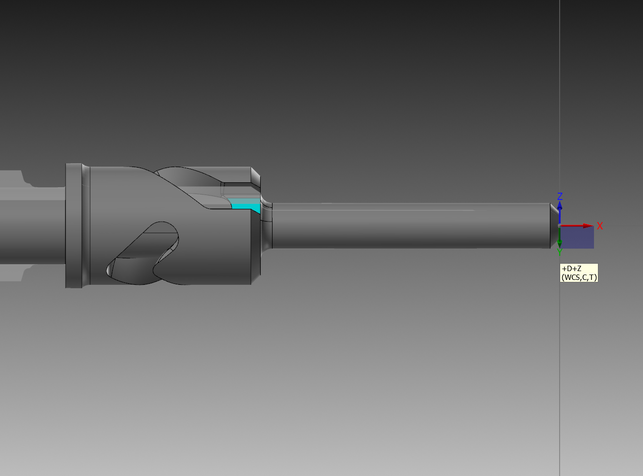
I took the floor shape and unrolled it. I then offset the shape the .1875 that is the fillet and then filleted the sharp corners the .1875. Once the outside shape was created I then used surface Extrude to make the Surfaces. This is similar to solid extrude where you get a close shape, I could have made this with solids then made surfaces from the solid shape, but since I have worked with surface models for over 30 years not a big deal to just work with surfaces. I then removed the top surface and filleted the floor sharp corners to represent the shape of the part that is rolled now unrolled.
I also did toolpaths where I drove the round part using the Unroll on the round model.
Another way to drive this toolpath is with surfacing toolpaths like I did with contour. In the old school toolpaths you have to click on the rotary axis, but it has been tore up for many versions and I quit using it years ago why I went with the contour toolpath like I did to mimic them.
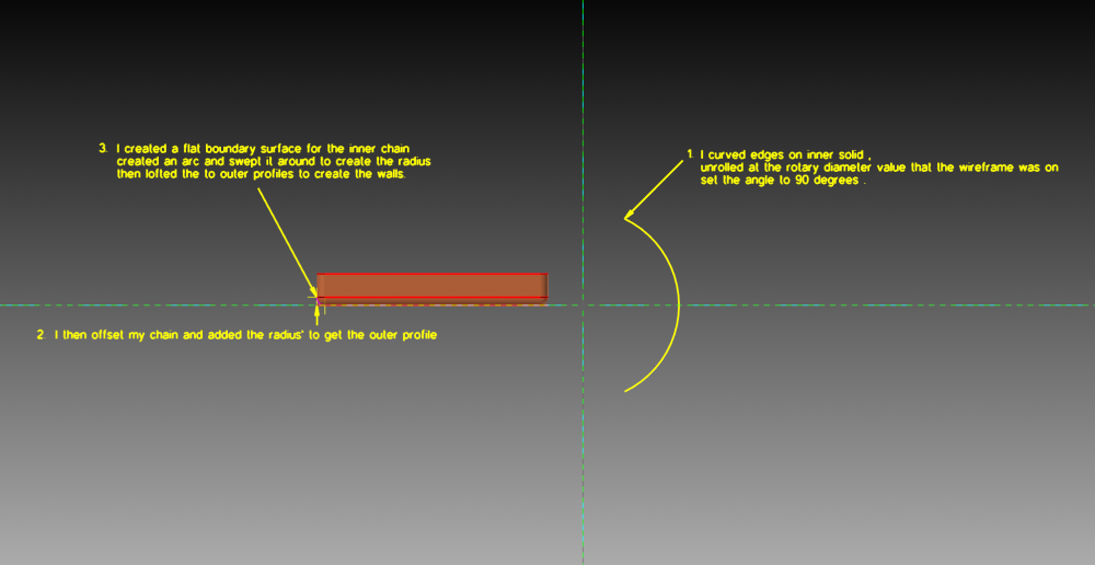
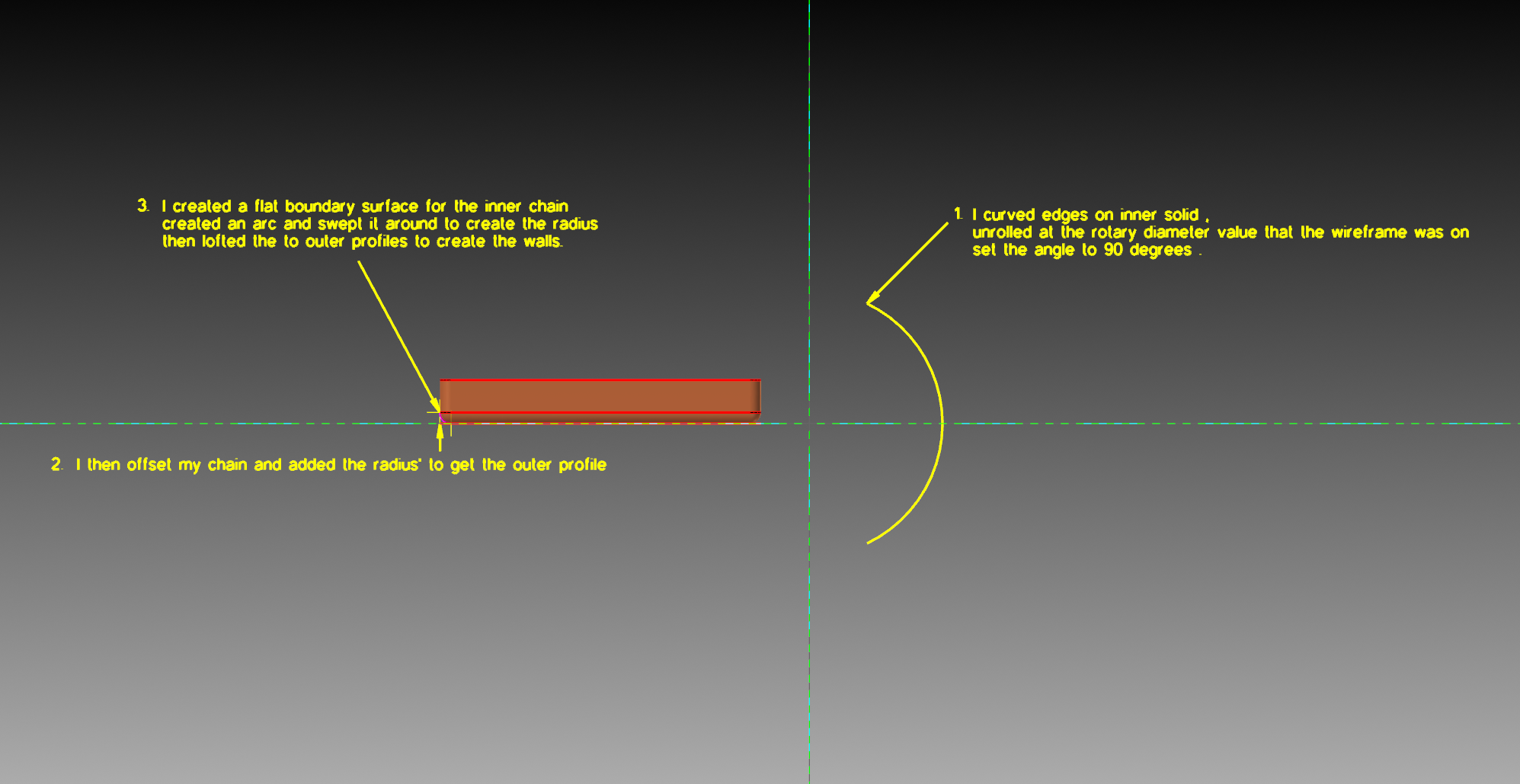
Perfect! the missing link for me was the "surface extrude" which was exactly what I was trying to recreate through flat boundary and loft. Which eventually did work but that coupled with me having to add wireframe and sweep for the rads' was about 5 steps longer then what you just taught me. Thank you very much for the help. It'll certainly save countless hours and headaches for me in the future.

-
1
-
-
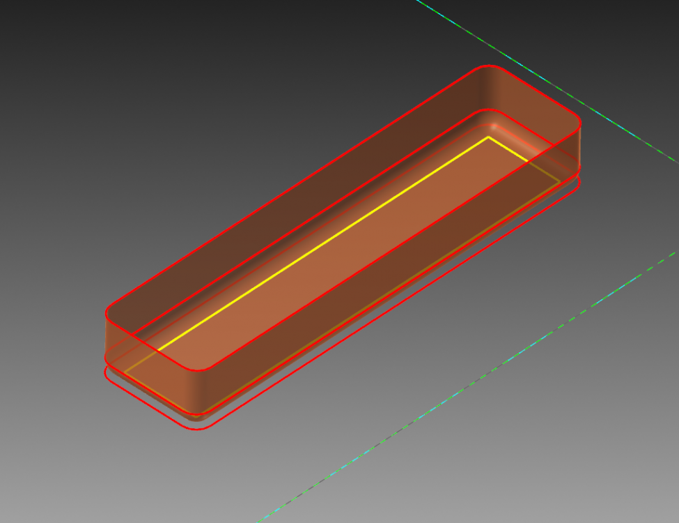
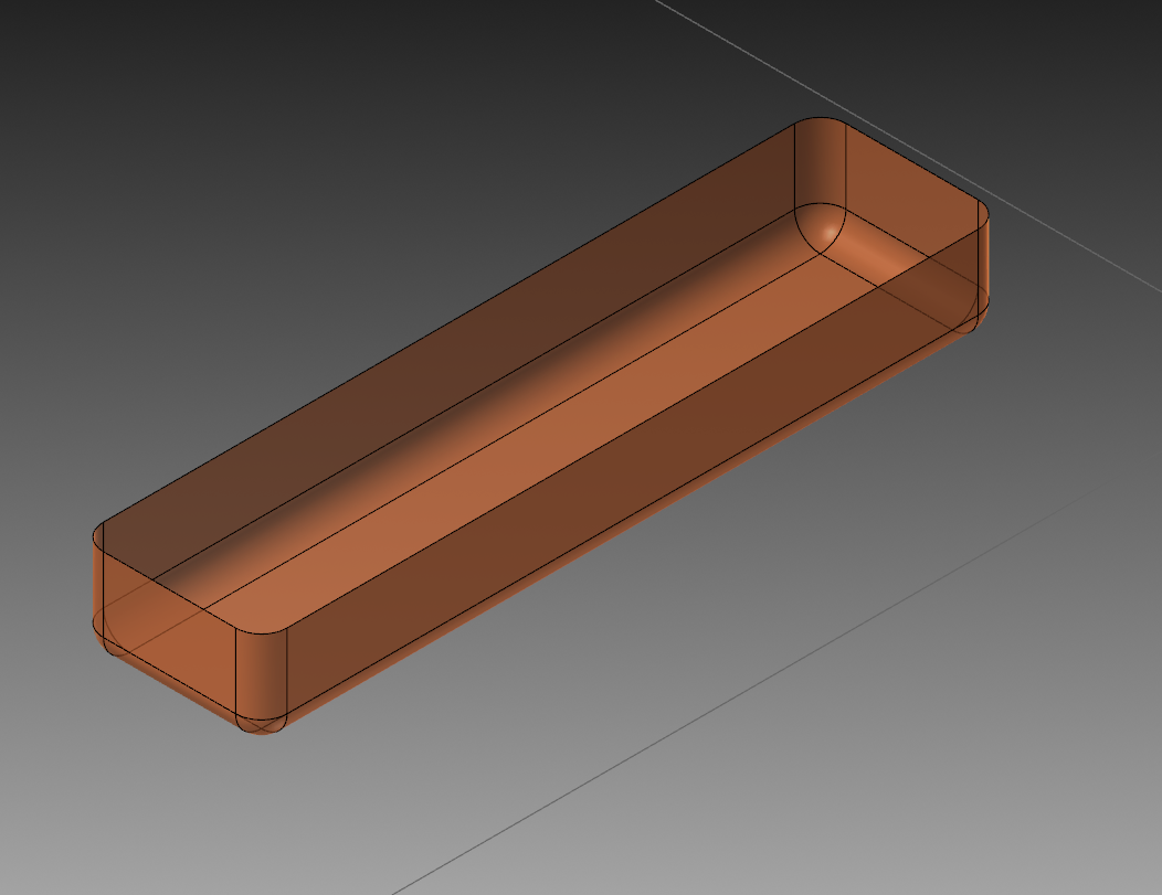
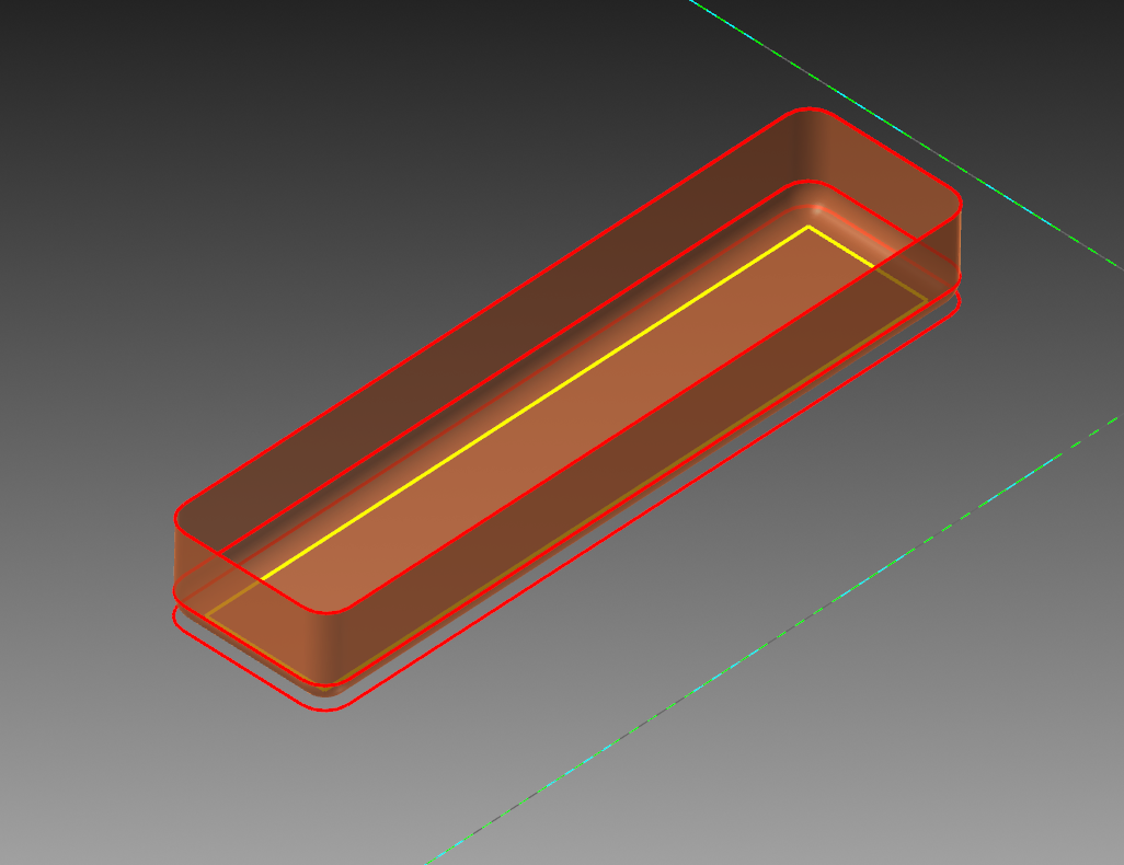
here's a better view of the surface I created.
-
I'm currently loving this post because I've been needing more experience in axis substitution for more advanced rotary work.
Once again Ron went above and beyond in providing some deep cut experience in doing this type of work. I do have some questions regarding the unrolled surfaces you created for toolpathing this. I gave it my best to recreate the process and I think I'm close but I also feel like I'm taking the extreme long road to get there.
There are also differences in my surface compared to yours where as yours is much more comparable to the actual features of the part. If you could spare just a few more moments of your time to explain how you went about creating the surfaces it would be greatly appreciated.
I'll include an image of what I did for comparison.
Thanks in advance.
-
1
-
-
9 minutes ago, Colin Gilchrist said:
My favorite ERP System is ProShop. It is cheaper and much superior to the other systems mentioned in this thread. Plus, they are US-Based, and their system makes is sooo easy to integrate your Quality System, and actually helps you to become AS9100 certified, because that is how the system is designed.
The best utilization of this system is to bite the bullet, junk it, and install ProShop. (Technically, install ProShop in parallel, get it working, see how much more amazingly productive your company becomes, and phase out your old ERP sooner, rather than later.)
I hope one day to find myself in the position here to do just that, until then I'll be doing as much research as I can to ensure a smooth transition for me and the team. There's just so many redundancies, it pains me to put effort into what I know is just an inevitable dead end for my company. I assumed when E2 announced that it was discontinuing updates to move forward as "jobboss" they would take the hint and switch it up.. but alas, here we are.. for now at least.
-
1
-
-
2 hours ago, gms1 said:
Garbage in, garbage out. In the end I am sure all these systems are fine but none of them will be if you don't use and maintain the system. We used E2 at a place I worked and it just turned into a time clock that looked like it came straight out of microsoft database circa 1994.
Currently going through the same thing
.. What frustrates me most is when I plead with management about how there are better ways to utilize E2 I am told I'm wrong by people who just don't understand and have never been formally trained to use the product.
-
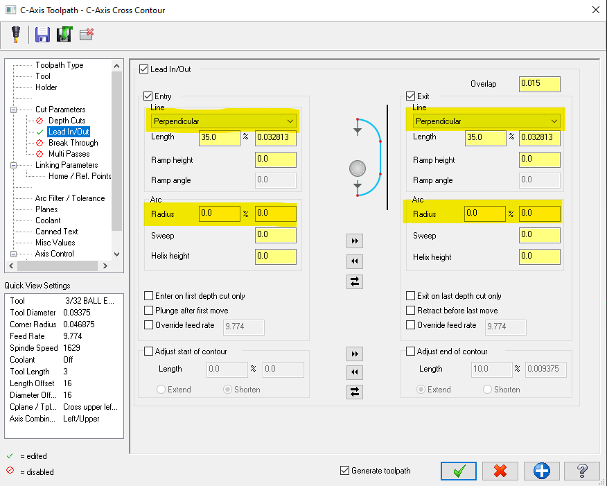
You can try setting your lead in/ lead out to Perpendicular entry with 0 radius. This will prevent it posting the g41 line on an arc move which alarms out my Haas controls.
-
1
-
-
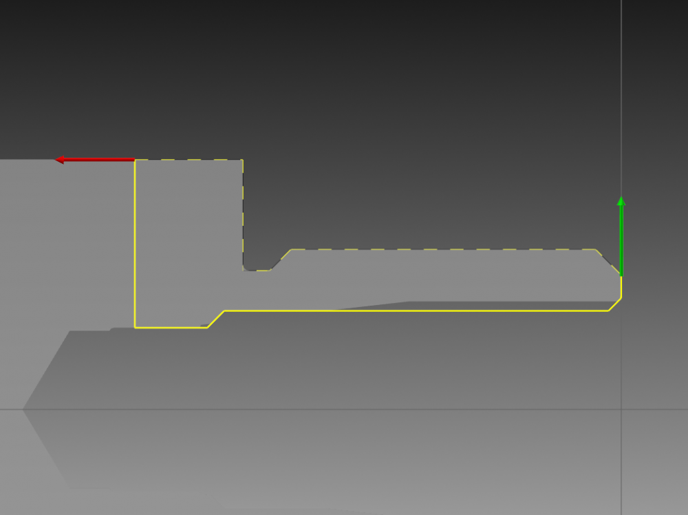
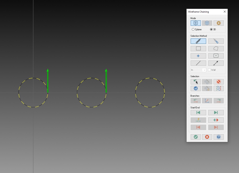
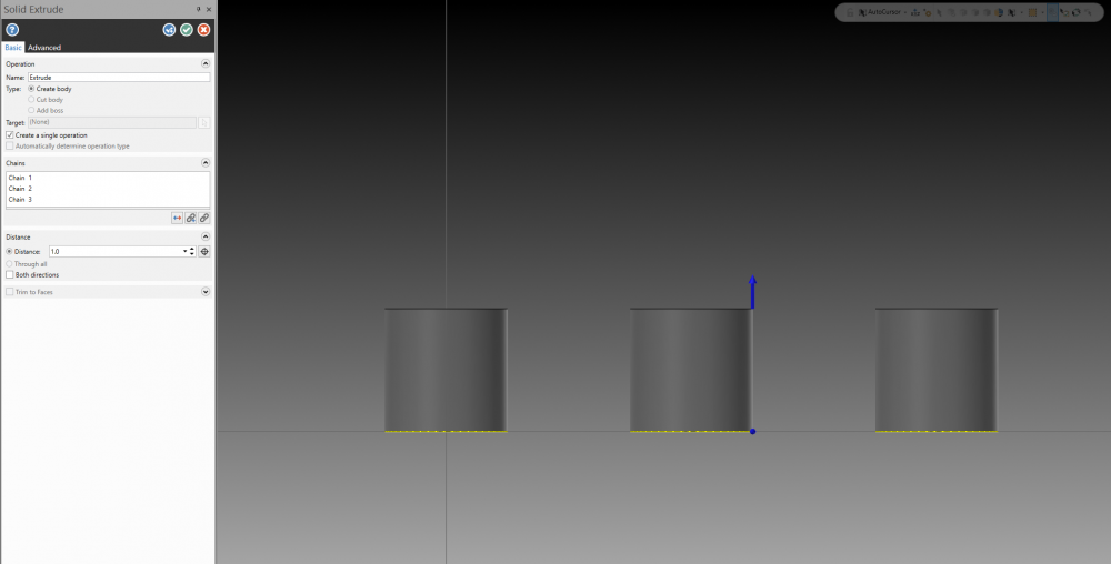
One example is in the cutting direction of your toolpaths. In the pic provided my tool will start at the front and cut from right to left following the chaining direction.
Another example is If you're looking to extrude solids in the same direction you'd want to keep the chaining direction the same in order to get the same result for each one.
-
9 hours ago, Matthew Hajicek - Conventus said:
Doubt it.
Have you turned off the display of toolpaths while regenerating?
is this setting located in configuration?


4th axis programing.
in Industrial Forum
Posted
Would it be possible to use transform rotate instead of creating multiple planes?