beej
-
Posts
516 -
Joined
-
Last visited
-
Days Won
4
Recent Profile Visitors
1,820 profile views


beej's Achievements
")


-
I appreciate your input Colin. it will help me with other customers to know that about Catia's tolerance defaults.
-
it would be easier for me to talk to Abe Lincoln. if something is going to change it will have to be on my end.
-
thanks for trying, Tom. its automotive. I didn't really want to give the maker, because I'd hate to complain about an otherwise GREAT customer.
-
step and parasolid. if you open up the step file in Notepad, you can see it was created in NX. the parasolid file was created in Solidworks, But I do not think either are the native files. When I researched the Manufacturer, I saw that they use Catia and that there was also an article about them creating their own cad software.
-
I think that is what is going on. It gets converted several times before it gets to us. But I'm betting the original file was Catia, which has been a conversion problem for as long as I can remember. We always gitter done. but it adds a lot of time.
-
thanks for the ideas, guys. I never heard of Spaceclaim, I'll look into that. and also try to find out the native format of these files.
-
that's a good point. I'm not sure what the native format even is. it's not easy to get that kind of information the American purchasing agents who don't seem to know a lot about their Japanese counterparts.
-
I"m wondering if anyone has had any luck using tolerances to help with importing solid models. we always have problems with solid models that come in from Japan. They always convert in as surfaces or open sheet bodies and the edges are all over the place keeping them from knitting together as a closed solid. There are too many layers of insulation between me and the people generating these solids to get any help from Japan. just wondering if there are tricks to help myself, that I'm missing.
-
thanks for all the input guys. A lot of really good ideas here. More than one way to skin a cat, I see. not that I'm into cat skins and such.
-
some Good ideas, guys, I appreciate the input. I've been kicking that wire edm idea around some too. I can't blame the designer too much on this. These aren't ejector blades, they are punches on a Trim die. Punching flash through a pocket on a casting. there are lots of different shapes and sizes beside the one that I showed in the pic.
-
we have tried ramping and constant z cuts. about the same result both ways, but I thought, as you did, that ramping would be the way to go. I have been using a 3/8 dia cutters with 5/16 shank. That is bigger than I would like but, the overall length of the pin keeps me from going much smaller.
-
that's a good idea, I'll give that a try. standing it up is the only option I have at the moment although it may come to getting a lathe with live tooling or a 4th axis
-
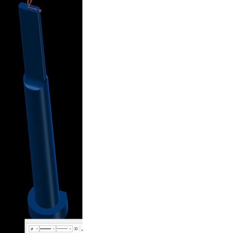
I'm having problems cutting the thin rib on the end of this pin. the pin comes pre hardened 50Rc. the rib is .088x.275 it stands up 1.75 tall. Straight walls (no draft). I'm stuck with the design. I only have 3 axis machines. We've been able to make them functionally right, but the customer is complaining about the chatter marks on the finish. so far I've tried using Millstar Backdraft cutters and reduced shank endmills to try and keep the chatter down but so far not much has helped. I attached a jpeg file so you can see what I'm talking about. Any ideas or processes that have helped you?
-
why? do I look familiar?
-
I am seeing the same thing shazaam, If i use all the same settings (step over, feedrates, etc) x7 takes twice as long as X6. Maybe it handles the last little bit of material, before the break out better. but the overall time in the machine is 2x as long.