RecceDG
-
Posts
55 -
Joined
-
Last visited
-
Days Won
3
Content Type
Profiles
Forums
Downloads
Store
eMastercam Wiki
Blogs
Gallery
Events
Everything posted by RecceDG
-
So i checked the configuration of my rapids in Mach 4, and I had the Z at 90 in/min and the X at 20 in/min. Those got bumped up to 175 in/min (!) and 35 in/min. X I increased because at 20 in/min max speed, at higher spindle RPM I started knocking on feed/rev limits that I might actually use - which could be a problem if I was moving both axis simultaneously, like cutting a chamfer or a radius. I presume Mastercam has some place in the machine configuration that specifies max axis speeds, so I gotta go find those and set them correctly. Another interesting question is - how fast (shaft RPM) can a steel screw be spun in a brass nut before wear becomes a concern? I haven't the foggiest idea of where to look that up. Textbooks on machine design? And I suppose threadform matters too. Any ideas?
-
Thanks. One does try and be entertaining, and my video production/editing skills are getting better with practice - much like my Mastercam skills!
-
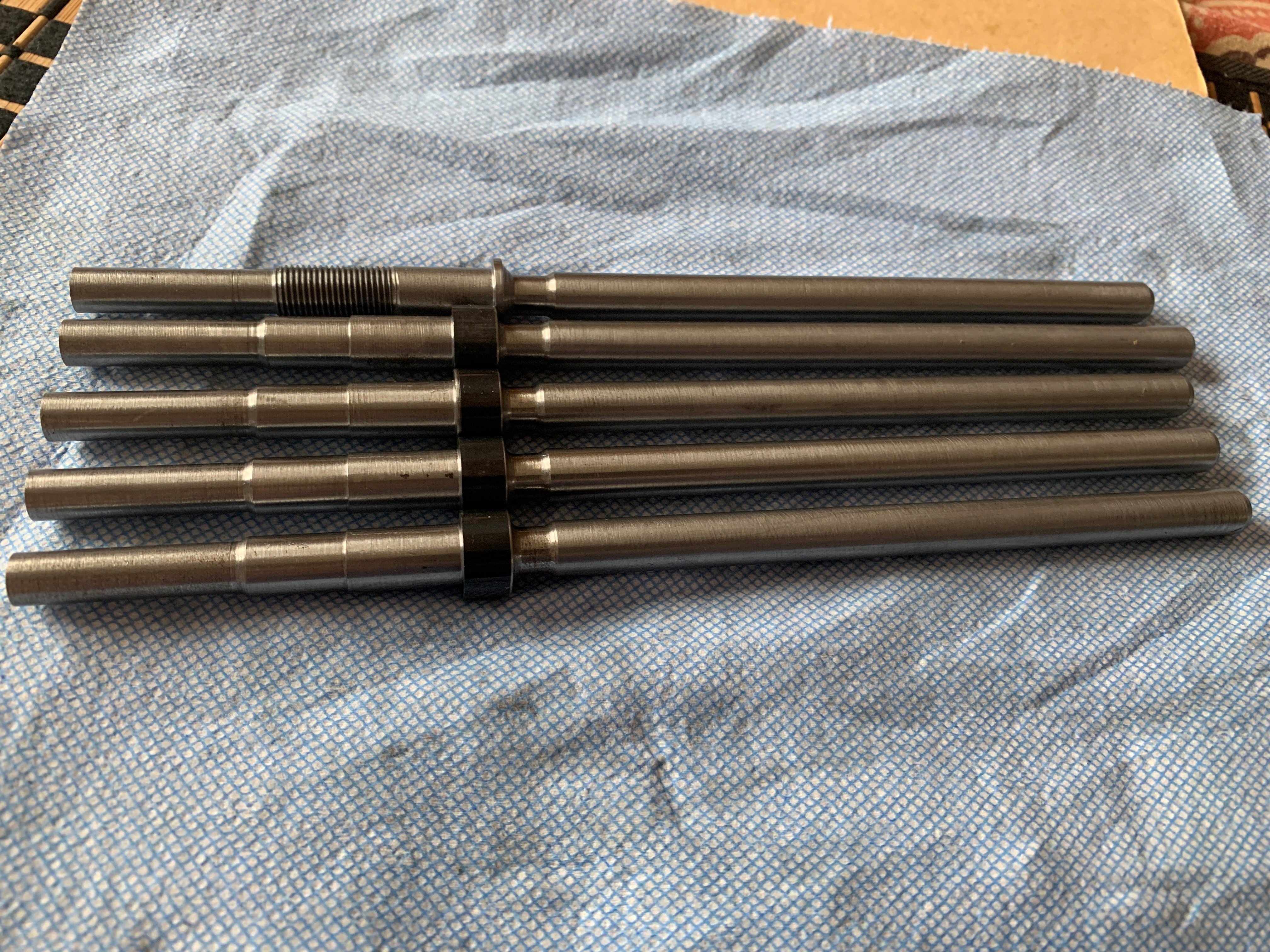
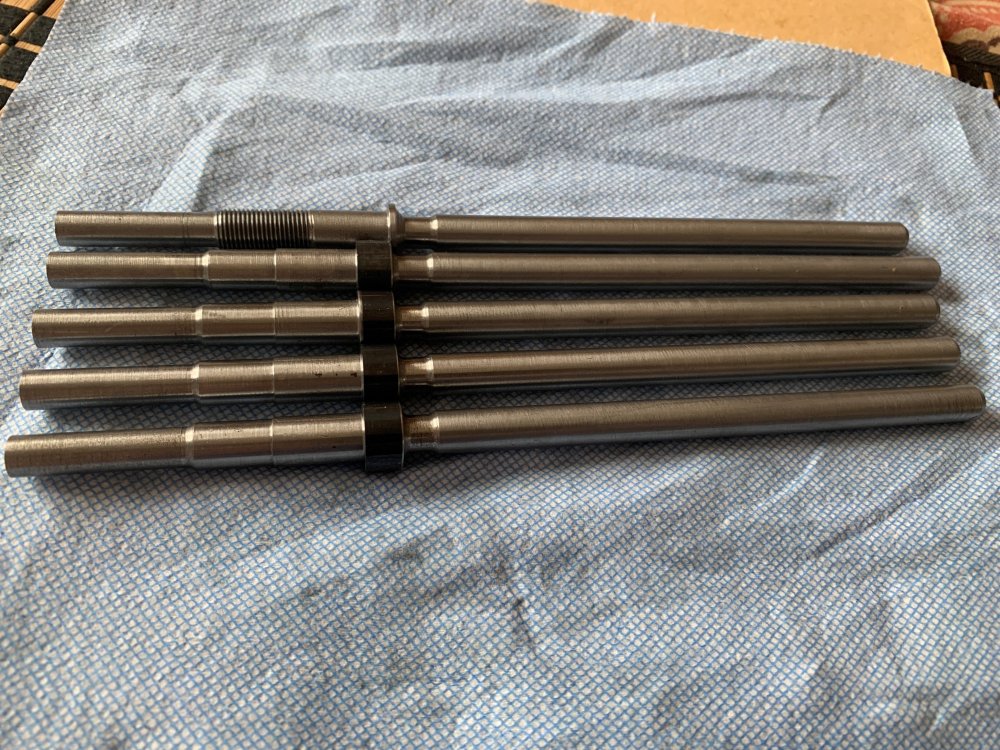
And the final result!
-
So success - top one was first prototype where it cut on an angle 'cause I fat-fingered the lathe plane; bottom 4 have the proper radius.
-
Sent. I gave you copies of both files.
-
Well as a refugee from Fusion 360, one of the things that Fusion does well (enough) is the marriage between CAD and CAM. I'm very much used to having them both in the same place. Back in my former life, Mike the Machinist ran MC Standalone and imported my parts out of SW. I see why he did that, but if I have the option to stick to one UI, I would prefer that. The other thing Fusion is good at is the "one licence, run anywhere" aspect of the cloud. My primary design machine is in my basement, my lathe (and soon, mill) are in the shop in an outbuilding, and the CNC router is in the garage. I do most of my design work on the "design studio" machine, but it has proven to be *very* useful to be able to pull up Fusion at the machine (all my machines are PC driven) to make tweaks. Solidworks lets me do this, Mastercam only allows one installation per licence. I really wish I could install MC on all 3 machines, and have MC limit me to one *running* instance at once.
-
Be happy to - what's the process to send it to QC?
-
Yup - because if I limit the selection to anything else except the "tires", the toolpath works. There is something specific to that geometry that Mastercam doesn't like, but (at this point) I don't know if it is an error in the Solidworks geometry that is making Mastercam (rightfully) barf, or if it something in Mastercam having trouble with legit geometry. And that could be a PEBCAK problem due to my unfamiliarity with MC, or it could be a legit bug. I also found something else related to a tool collision not being detected, but one step at a time.
-
Tried that. Did nothing.
-
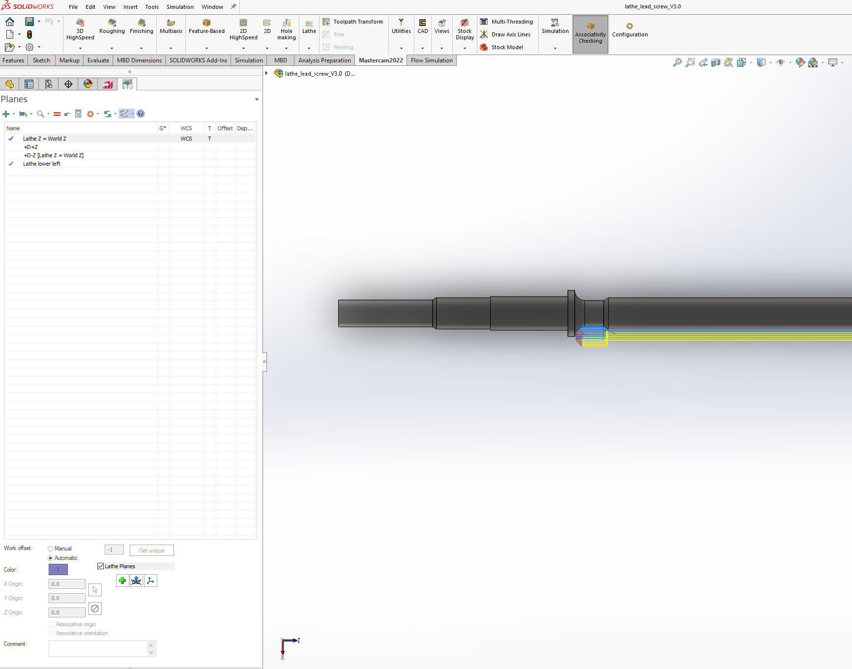
That is lower left turret land. What makes you think it is upper? For fun, I created a new part. Same process - rotate Solidworks view around until Z and X point the right way, draw a sketch in this view, revolve it, but this time, no undercuts. And "Lathe rough" worked. The toolpath is a little janky because I was trying to force a tool in that doesn't fit... the point is though that the toolpath creation is clearly recognizing the model geometry and is doing the right thing. So either the problem is with the undercuts, or there's something wonky with the geometry of the model itself.
-
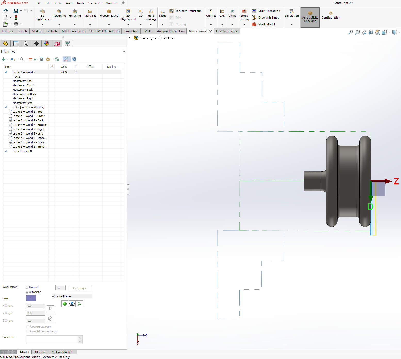
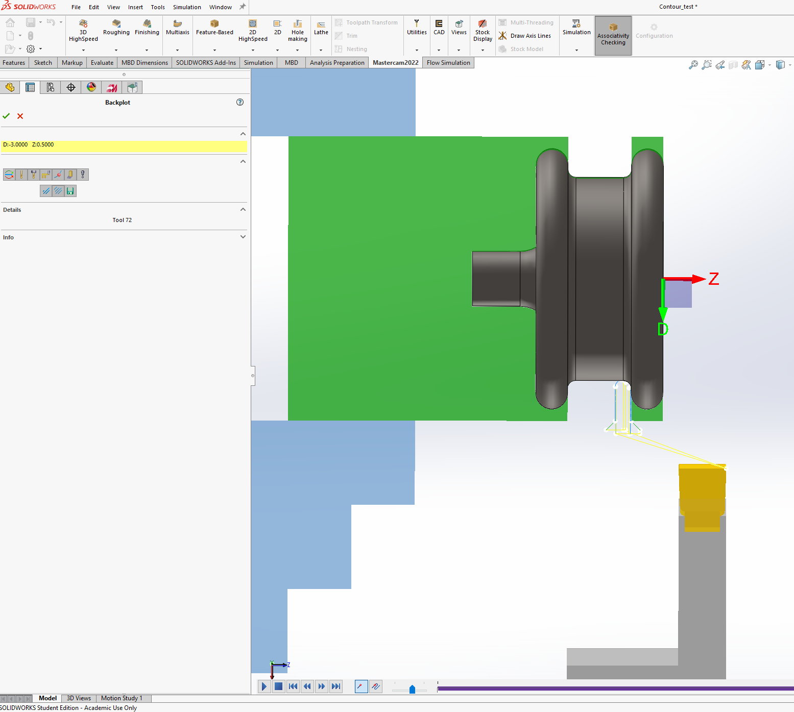
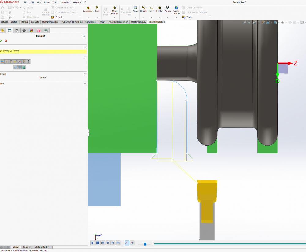
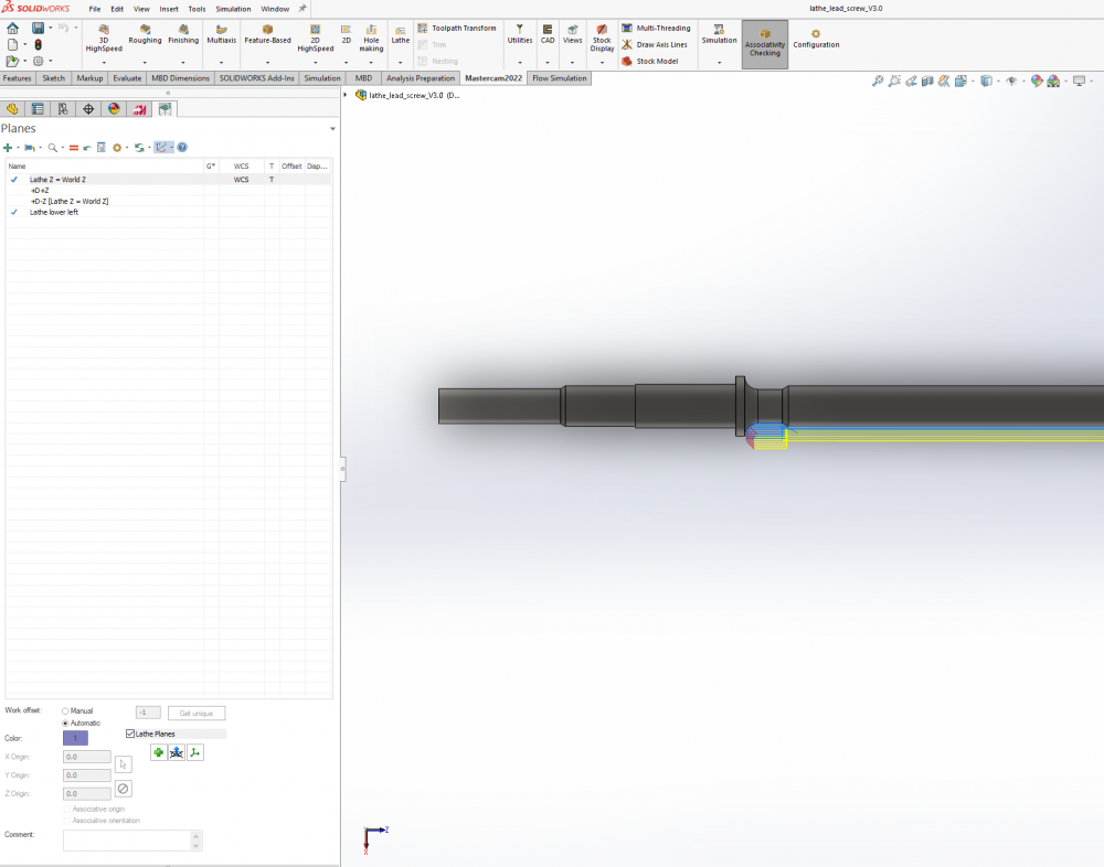
Screengrab of planes manager. I mucked around setting various planes to WCS and T with the "=" button, but none of them fixed that chain. Then I tried a groove operation, selecting the faces between the "tires" - so the big turn flat, the two fillets on each side of it, and the little tiny facing flat as the groove blends into the "tires" - and that worked! So then I did a second groove op, this time on the "axle" and the "bell" radius, and it kinda worked, in that it correctly cut the "axle" and "bell", but to do so it plunged straight through the "tire". It's like it doesn't see that part of the model - like the "tire" doesn't exist.


-
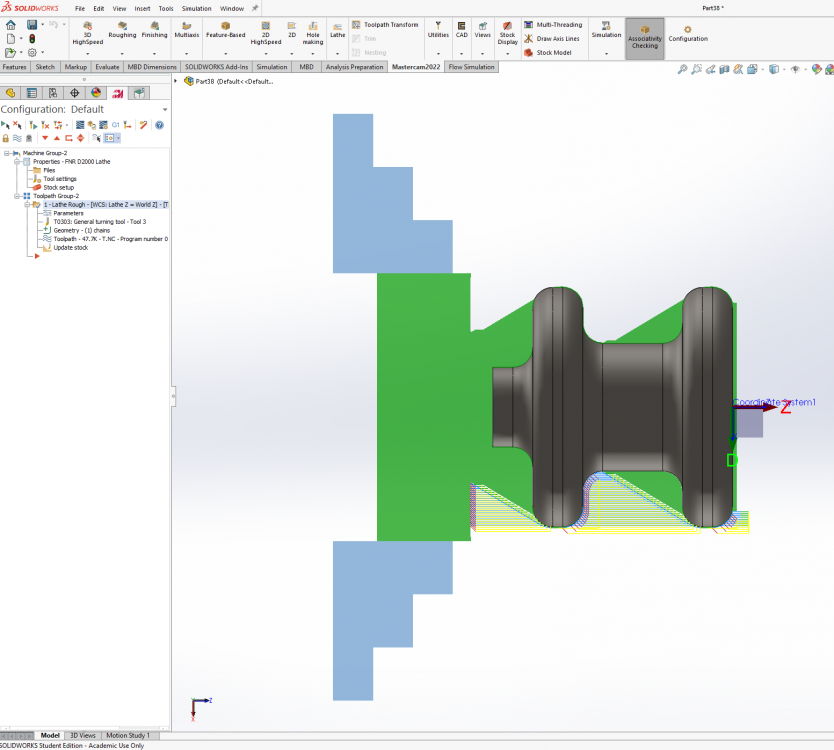
The machine definition is left spindle, lower turret. Stock setup and chuck jaws setup worked fine right from the hop. Lacking "Align to Z" I rotated the Solidworks view around to orient the world X and Z axis in the right direction and created the sketch on that plane, which worked for setting up the stock. A facing cut works as expected - tool comes in the right way, oriented correctly, and stops at the rightmost edge of the model. Maybe this is plane related - I didn't touch anything in planes manager; I'll check that and see what it is currently set to.
-
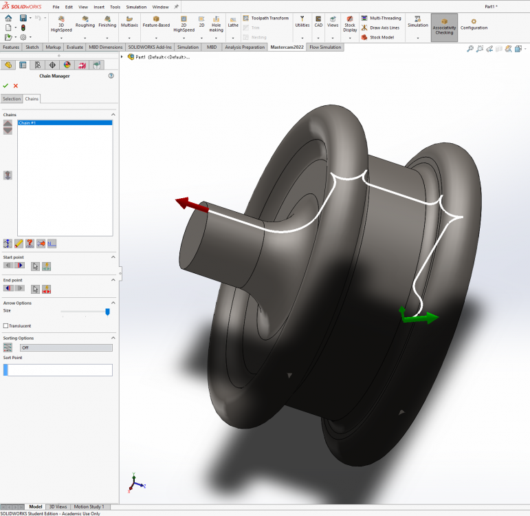
So why is THIS happening? I drew up a part with a bunch of curves so I could test my post for G2/G3 correctness, but I can't get the chain to follow the outside profile of the part. No matter how I select the faces, the chain cuts inside the "tires" on this shape, instead of going around the outside. The Solidworks geometry is just a revolved sketch.
-
Caught a mistake! G18, not G17...
-
Ha! Misc Integer 1 set to 1 fixed the G28 stuff, and some post processor tweaks fixed the rest. Voila! % O0000 (PROGRAM NAME - LATHE_LEAD_SCREW_V3.0_OP3) (DATE=DD-MM-YY - 05-08-21 TIME=HH:MM - 22:01) (MCAM FILE - M:\DOCUMENTS\DENNIS\SOLIDWORKS PROJECTS\LATHE_LEAD_SCREW_V3.0.SLDPRT) (NC FILE - D:\DOCUMENTS\MY MASTERCAM 2022\MASTERCAM FOR SOLIDWORKS\LATHE\NC\LATHE_LEAD_SCREW_V3.0_OP3.NC) (MATERIAL - STEEL INCH - 1030 - 200 BHN) G20 G0 G54 G17 G40 G80 (TOOL - 3 OFFSET - 3) (TOOL 3 INSERT - DCMT32.51) G0 X1. Z-5. T0303 M6 G97 S2500 M03 G0 X.4815 Z-5.0751 G99 G1 X.4621 Z-5.0926 F.006 X.3031 Z-5.236 Z-5.4472 G3 X.5081 Z-5.5497 R.1025 G1 X.5281 Z-5.5324 G0 X1. Z-5. M05 M30 %
-
Yay! I'm helping!
-
After some mucking about with the toolpath parameters and the control definition, I got to here: % O0000 (PROGRAM NAME - LATHE_LEAD_SCREW_V3.0_OP3) (DATE=DD-MM-YY - 04-08-21 TIME=HH:MM - 21:48) (MCAM FILE - M:\DOCUMENTS\DENNIS\SOLIDWORKS PROJECTS\LATHE_LEAD_SCREW_V3.0.SLDPRT) (NC FILE - D:\DOCUMENTS\MY MASTERCAM 2022\MASTERCAM FOR SOLIDWORKS\LATHE\NC\LATHE_LEAD_SCREW_V3.0_OP3.NC) (MATERIAL - STEEL INCH - 1030 - 200 BHN) G20 (TOOL - 3 OFFSET - 3) (TOOL 3 INSERT - DCMT32.51) G28 U0. W0. G50 X1. Z-5. G0 T0303 G97 S2500 M03 G0 X.4815 Z-5.0751 G99 G1 X.4621 Z-5.0926 F.006 X.3031 Z-5.236 Z-5.4472 G3 X.5081 Z-5.5497 R.1025 G1 X.5281 Z-5.5324 G28 U0. W0. M05 T0300 M30 % So I found: - how to switch to/from CSS mode - how to control coolant - how to get arcs to use radius mode instead of I K Left to work out: - how to get an M6 on the tool change (force tool change checkbox didn't do it) - how to get rid of G28 and use a regular G0 rapid - Why there is a T0300 at the end of the program - How to get my safe start block prepended
-
I'm using the generic FANUC post.. but ack, I'll take a look at that. I also see there is a coolant button which undoubtedly lets me switch between flood/mist/no coolant. I figure about half of the "problems" with my posted code are just path parameters not properly set, and the other half are postprocessor tweaks. I had a similar experience with Fusion.
-
Huh. Must be an edit time limit - I had intended to edit out the GCode and do the analysis separately. OK, let's take a look, using this as reference: Mach4 Lathe GCode Manual.pdf (machsupport.com) O0000 (PROGRAM NAME - LATHE_LEAD_SCREW_V3.0_OP3) (DATE=DD-MM-YY - 03-08-21 TIME=HH:MM - 23:13) (MCAM FILE - M:\DOCUMENTS\DENNIS\SOLIDWORKS PROJECTS\LATHE_LEAD_SCREW_V3.0.SLDPRT) (NC FILE - D:\DOCUMENTS\MY MASTERCAM 2022\MASTERCAM FOR SOLIDWORKS\LATHE\NC\LATHE_LEAD_SCREW_V3.0_OP3.NC) (MATERIAL - STEEL INCH - 1030 - 200 BHN) G20 [INCH MODE - yup] (TOOL - 3 OFFSET - 3) (TOOL 3 INSERT - DCMT32.51) G28 U0. W0. [Hm. G28 for Mach uses Format: G28 X__ Y__ Z__ A__ B__ C__ where the number after the axis is the intermediate point.] G50 X1. Z-5. [In Mach, G50 is min/max spindle speed for CSS mode. X1, Z-5 is the home position I specified, so this line and the previous are setting the home position] G0 T0303 [Not sure why there is a G0 here... Tool pre-call is right, but doesn't include the M06 tool change] G97 S1587 M03 [Constant speed mode, not quite 1600 RPM, turn spindle on - weird speed, where is this coming from?] G0 X.4815 Z-5.0751 M8 [Rapid to start point, turn coolant on - need to change this to M7 because I have mist, not flood - machine config?] G50 S2800 [g50 again - but this time it is right - set max speed to 2800, which is my configured max spindle speed] G96 S200 [CSS mode 200 ft/min - I thought I had this set to a flat speed in the operation params, have to check] G99 G1 X.4621 Z-5.0926 F.006 [Set feed as per-rev, then start cutting] X.3031 Z-5.236 Z-5.4472 G3 X.5081 Z-5.5497 I.1025 [Arc move.No K? Mach manual goes on at length about arcs and has G90.1 and G90.2 to switch between absolute and incremental modes. Going to have to see what this toolpath looks like in Mach's visualizer to see if this is OK] G1 X.5281 Z-5.5324 G28 U0. W0. M05[Try to go home but wrong format for Mach - and dangerous on my machine - Spindle off] T0300 [Why does it try and return to tool offset 0 here?] OK, so based on this, here is what I think the program should look like. How many of these are config switches, and how many require editing the post processor? % O0000 (PROGRAM NAME - LATHE_LEAD_SCREW_V3.0_OP3) (DATE=DD-MM-YY - 03-08-21 TIME=HH:MM - 23:13) (MCAM FILE - M:\DOCUMENTS\DENNIS\SOLIDWORKS PROJECTS\LATHE_LEAD_SCREW_V3.0.SLDPRT) (NC FILE - D:\DOCUMENTS\MY MASTERCAM 2022\MASTERCAM FOR SOLIDWORKS\LATHE\NC\LATHE_LEAD_SCREW_V3.0_OP3.NC) (MATERIAL - STEEL INCH - 1030 - 200 BHN) G20 G0 G54 G17 G40 G80 [Safe start line - Rapid mode, fixture offset 1, ZX plane, turn off nose compensation, cancel canned cycles] (TOOL - 3 OFFSET - 3) (TOOL 3 INSERT - DCMT32.51) T0303 M6 [Select tool 3 and execute change] G0 X1. Z-5 [Normal rapid move to user-defined home with no G28 nonsense] G97 S1587 M03 [Turn spindle on. I guess it uses G97 to keep the spindle RPM from surging during the prelim move - but where did 1587 RPM come from?] G0 X.4815 Z-5.0751 M7 [M7 vs M8 is almost certainly a machine config switch somewhere] G50 S2800 G96 S200 [Need to verify where this came from in the toolpath config, but is OK] G99 G1 X.4621 Z-5.0926 F.006 X.3031 Z-5.236 Z-5.4472 G3 X.5081 Z-5.5497 I.1025 [Probably OK - need to verify] G1 X.5281 Z-5.5324 M05 M09 [Shut coolant off too] G0 X1. Z-5. [Normal rapid back to home] M30 %
-
OK, I'm looking everywhere in Mastercam for Solidworks 2022 and I can't find "Align to Z" anywhere. Where is it hiding? Placeholder: This is the GCode the final finishing pass generated when I posted it. I'm going to analyze it later. Pay no attention just yet. % O0000 (PROGRAM NAME - LATHE_LEAD_SCREW_V3.0_OP3) (DATE=DD-MM-YY - 03-08-21 TIME=HH:MM - 23:13) (MCAM FILE - M:\DOCUMENTS\DENNIS\SOLIDWORKS PROJECTS\LATHE_LEAD_SCREW_V3.0.SLDPRT) (NC FILE - D:\DOCUMENTS\MY MASTERCAM 2022\MASTERCAM FOR SOLIDWORKS\LATHE\NC\LATHE_LEAD_SCREW_V3.0_OP3.NC) (MATERIAL - STEEL INCH - 1030 - 200 BHN) G20 (TOOL - 3 OFFSET - 3) (TOOL 3 INSERT - DCMT32.51) G28 U0. W0. G50 X1. Z-5. G0 T0303 G97 S1587 M03 G0 X.4815 Z-5.0751 M8 G50 S2800 G96 S200 G99 G1 X.4621 Z-5.0926 F.006 X.3031 Z-5.236 Z-5.4472 G3 X.5081 Z-5.5497 I.1025 G1 X.5281 Z-5.5324 G28 U0. W0. M05 T0300 M30 %
-
OK, I'll give that a try. Thanks.
-
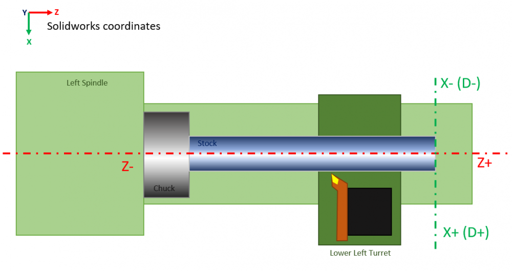
OK, since I have your attention. Attached is a quick sketch of my lathe setup and how I (and Mach 4) see the layout once everything is correctly set, just so we have a frame of reference for the discussion. Assume that I drew the part in Solidworks (I'm using Mastercam for Solidworks as my workspace, not standalone). Assume that I drew the part in the orientation of the gnomon in the upper left of the sketch - and for giggles, let's assume that that gnomon is also the Solidworks origin for the part (ie I haven't used the hack I described above) so I have to move the WCS to where it is on the sketch. Do I select the rightmost part face and hit "Align to Z" and that does it? Now what if I want to do a second setup where I flip the part in the chuck. Select the leftmost face, "Align to Z" and maybe transform? I'm trying to wrap my head around this whole planes thing. In my head, the lathe plane is fixed and the part axis flips around. I kinda want to be able, for each setup, to define which way part Z points, and then Mastercam aligns that Z direction with the fixed lathe Z direction (which is how Fusion works). This is as much a terminology/UI problem as anything else; I have to learn to speak Mastercam.
-
If this works out for you (and I suspect it will) consider reaching out to the business school of your local university and asking them do see if someone wants to do a case study on your process. A published paper by an influential school means you could have effects felt far beyond just your shop.
-
So an update: Like all things, life gets in the way. Notwithstanding my background, I am a home gamer; I can't necessarily shut my life down for a week (or more!) while I concentrate exclusively on learning a new software package (especially one that isn't my day job). But as luck would have it, a project came up. I'm making a new leadscrew for the cross-slide on my lathe. In order to get leadscrew-quality threads, I'm sending it out to be threadrolled, and the threadroller has specific requirements that must be met. One of those is a 30 degree bevel off the backside of the threaded portion, then the shaft flares out to form a bearing retention shoulder - and because my former racing engineering life taught me to "radius all the things" to prevent stress raisers, that transition is radiused. Lathe work is generally so simple that most of my stuff I do in MDI mode, but when profiles get more complicated, I go to CAM. I did a couple of parts like this in Fusion, so I know how to make Fusion lathe toolpaths and I have a workable Fusion lathe workflow. In this case, I MDI-ed the main threaded section (where I had to hold +0.0, -0.0015") and now I want to generate toolpaths to hollow out that back chamfer, a little straight section, and the radius up to the bearing shoulder. I had originally drawn the part in SW as a series of stacked extrudes, but my spidey sense went off, and I re-did it as a single revolved sketch with the axis of revolution lying along SW's native Z axis. Unfortunately, I didn't notice that I had positive Z in the wrong direction - but more on that later. Then I had to do a machine definition. Some of this was pretty straightforward, some of this was unbelievably obscure (holy hell changing a machine to be inch, not metric is SUPER counterintuitive and much Google-fu was required) but eventually I wound up with an inch lathe machine with a left-side spindle and a lower left "turret" (my machine is a converted bench lathe, not a slant-bed) with the axis seemingly properly aligned. No physical model, just the definition. Then I defined tool 3 in my tool library - started doing it by hand, then I discovered where the standard tools lived and just pulled up the right one. Stock setup was straightforward enough, but I could not get the chuck to show up on the right end (WARNING!) . Started adding toolpaths. Some weirdness with defining the home position (why does it want a negative value of X to put the tool on the near side of the workpiece?) but I eventually got three created: a roughing path that replicated the MDI work I had already done (to get rid of stock crash warnings), a roughing path to hollow out the profile, and a finishing path that traced out the final profile. Toolpaths looked good and I could see in the backplot that radius compensation on the insert was working. So at this point I'm a few hours in, and I'm feeling pretty good. Not as intuitive as Fusion in some places (give the devil his due, HSMworks is pretty slick - but in some cases, I suspect Fusion/HSMworks may have copied MC) but I've got toolpaths that look reasonable for what I want to do. So I tried posting. My lathe is controlled by Mach 4, which is a FANUC (ish) clone. I'm using the generic FANUC post, and I'm fully prepared for weirdness here. Part of my Things to Do plan involves going through the postprocessor and disabling features that Mach 4 doesn't support or otherwise tweaking, and that wasn't on the agenda yet. Posting at this point was more to see what MC4SW would generate as code - and lathe programs are usually really short, which means that hand-editing them as a workaround until the postprocessor is sorted isn't a crazy idea. At this point, I'm not planning on running this code, I'm curious about if code will be generated at all. The program comes up... and yeah, there's a couple of weird things in the preamble that will need investigation, but I can see the actual passes and they look good and... hey, why are the Z values all positive? Z0 is the rightmost face of the part; everything Z should be negative.... Oh crap - the Z arrow on the gnomon is facing the wrong way. This resulted in a couple of hours banging my head trying to figure out how to flip the Z axis - made more difficult by the "Plane Manager" having moved out of the ribbon (as it is in the videos I found) into the side pane... and even then, NOTHING I could do would move the WCS. Plane manager, new plane, select part end face, click the '=" button to select it as the WCS, fully expect to see the gnomon jump... NOPE. NOTHING worked. I eventually went back to the original SW sketch, mirrored it, and set the rightmost end of the axis of revolution to be coincident with the SW origin, and THAT worked... but that feels like a hack. There has to be a way to assign WCS independent of the part's native axis orientation (otherwise how do you do a second setup where the part is flipped in the chuck? - this is one area where Fusion kicks xxxx in the UI department) And of course, after changing the native geometry, I had to go back and re-assign the geometry chains and flip the handedness of the toolholder and the stock - and now the chuck is on the correct side - but pointed the wrong way? (something to investigate) but I have reasonable-looking toolpaths again. So, progress.
-
I don't know if all y'all pros know this, but there has been a HUGE explosion in consumer-level CNC in the past couple of years. Mostly 3-axis gantry routers like XCarve, Shapeoko, 3018 etc but also lots of user-converted small lathes and mills. You can get an Arduino shield that runs GCode (GRBL) or OTS components like the Ethernet SmoothStepper and Mach 4, slap on some stepper motors, and go to town. Most machine vendors have their own design software, but it universally sucks, so the next level up for a hobby CNC guy is something that generates GCode. Autodesk went after this market HARD with Fusion 360, reaching out to individual users (like me) or through tie-ins with popular YouTubers like NYCNC and AvE. They got a lot out of it too, utilizing their user community as product testers (Fusion got WAY better from when I first touched it in 2017 to today, boy howdy, thanks to huge user uptake and all the bug reports and diagnostics). You go to any general-purpose social media site that has a hobby CNC corner on it (like Reddit) and Fusion has *enormous* mindshare because of this. But Autodesk gonna Autodesk, and now that Fusion is more ready for primetime and the pro market, they have started squeezing them that got them there - and I'm one of "them". So there is a growing movement/realization amongst people like me that cloud computing CAD/CAM is super vulnerable to the corporate whims of those in charge and that features and access can and WILL be pulled at any moment - and they want an alternative. I'm lucky, in that I came to CAD/CAM by way of the pro side from my job in my former life. I used Solidworks daily, and I used Mastercam (by association) through my partner machinist. So I knew Mastercam existed, and I had a rough idea of what it did and how it did it. So I came looking for Mastercam, fully expecting that it would be priced as far out of my price range as a full seat of Solidworks. The Titans of CNC promotion was a welcome surprise, and here I am. It is now possible to get a full version of Solidworks Educational (fully functional except for a watermark in your drawings - all the add-ins are there) for $50/year. And with the Titans Mastercam promotion, that's CAD/CAM for just over $200 - or 1/3rd what Fusion 360 now costs *without* the good 3D toolpaths (that's another grand). The limit is the "make no more than $1500/year" stipulation, but that's easy enough to meet. (Although lots of hobby guys think they are going to get rich cutting "Live, Laugh, Love" plaques and then discover there's 10 other guys in their neighborhood trying the same thing) There is a real place for a hobby version of Solidworks and Mastercam, priced at hobby levels (which starts to get picky at the $200 price point and is running away at $500), and it's a good investment because that's basically mindshare and training in your ecosystem. If it becomes possible for a hobby guy to get Mastercam for his hobby machine at hobby prices - that's training for if/when he becomes a pro operator. Wouldn't it be great for pros to have access to a pool of potential employees already trained up? A rising tide floats all boats. It worked super well for Autodesk, turning Fusion from a joke to an actual player. The trick of course is differentiating the hobby version from the pro version. One COA is to restrict features, and to a degree, I'd be OK with that. So long as I get access to all the cool HSM 3D toolpaths that the big boys do (I want to speed up my operations as badly as anyone) I don't need 5 axis (or more) on a mill, or secondary turrets or live tooling on a lathe. There are no hobby mill-turns (yet...) But I kinda think this is the wrong path, because of the training/familiarity aspect. The other COA is to restrict support, and that makes perfect sense. I do not need an answer in 30 minutes. I have no expectation of getting a service call (although to be honest, the developer of the plugin for Mach 4 that controls my Ethernet Smoothstepper has remoted into my machine to diagnose a bug we saw on my lathe, so even that isn't fully off the table) but I get that I'm going to be way down the support priority list compared to a pro seat and that's fine. TANSTAAFL. But however it happens, I'm glad to have this option. I'm happy to pay for what I get, so long as the price remains reasonable and the functionality remains. I'd be even happier if it was a perpetual license - by which I mean, I buy MC2022, I get any updates to 2022 for free, and it never stops working, but if I want 2023, I have to pony up again (Magix uses this model for Vegas Pro, the movie editing software). I also wish I could use MC on multiple computers (although not simultaneously) because I have a computer at each machine, controlling it, and the one really useful feature of Fusion being cloud-based was that I could bring Fusion up at the machine to tweak geometry and toolpaths. Solidworks lets me do this, MC does not without first deactivating it on one machine then reactivating it on another (which I am hesitant to try, because I really don't want to somehow screw it up and have *nothing* work). I also would like an upgrade path on a continuum between "<$1500/year sales" and "full-bore seat" in case the "Live Laugh Love" plaques take off, with some sort of sliding scale of support to go along with the sliding scale of price. But at the moment, I'm glad to have what I have, I'm cool with the limits imposed on me, and I'm super keen to see it help more people migrate off of Fusion. I would very much like to be part of the conversation about what the hobby market means to Mastercam - And I think there's a real opportunity here for the company. Aside ends - back to learning.