


Kyle F
-
Posts
173 -
Joined
-
Last visited
-
Days Won
2
Content Type
Profiles
Forums
Downloads
Store
eMastercam Wiki
Blogs
Gallery
Events
Posts posted by Kyle F
-
-
You can create another level, label it "stock model stock" or whatever, and then while that level is active, right click the stock model--mill toolpaths--stock model convert to mesh.
Now the level will be populated with a model that you can then select from the little mouse icon under 'stock selection'
What is really nice about this, is that you can have multiple pieces of stock selected, if you're trying to prove out a tombstone program with toolpath transforms, etc. Definitely comes in handy.
Just gotta remember now if you change a strategy (that would change the stock models shape/size), you'll have to go back and delete the old stock model mesh, and re-do the process to update the stock to reflect the true stock model
-
 1
1
-
-
The operator is wild, I would love to see his train of thought that led him to this conclusion.
Sadly I am lacking in understanding of exactly how a lot of machine control functions actually work LOL, but I get the gist of G68.2 (G54.4 I definitely need some reading material)
Now, tool length offsets, and how changing the offset will effect the part/program? that's about as F'ing basic as it gets. Apprentice level stuff. Should be an easy choice IMO, and to understand it you don't have to worry about euler angles and rotary toolpaths and center of rotations, etc.
With that being said,... more than a few operators at my shop have suggested much worse

-
 2
2
-
-
5 hours ago, Newbeeee™ said:
I wonder if this is anything to do with liability of data - "print is master"?
They (Customer) may have been previously burnt by "designer" modelling inaccurate and machine shop making to model and it doesn't meet print....There was a TONNE (note metrico - larger than imperial :lol:) of this going on where "designers" didn't understand or couldn't comprehend the need for accuracy, or just didn't care.
Yeah that could be possible,.. Most of the time the CAD models that are given to me aren't nominal anyways,.. a 1.000 +.002/-.000 is usually modeled at 1.000 (those sort of things) but generally speaking locational tolerances are good. If I'm drawing in mastercam I feel like it's way easier for me to just misinterpret the drawing or fat finger a location/size (and I am definitely no GD&T expert)
5 hours ago, Newbeeee™ said:How accurate is pdf to cad - does that take the dimension to drive wireframe? Or pdf3d to model - again does this take the actual dims (unsure how smart a pdf is - prolly not?)
I know I definitely wouldn't trust it haha!
-
4 minutes ago, JParis said:
I certainly hope your front office is quoting that NRE for that work
I have tried to push for it,.. but we are not. New "big" customer, they want a small family of parts, supposedly around half a mil per year of work so we are doing it on the house. Makes no sense to me but I'm just a measly paid-by-the-hour programmer.
-
1 hour ago, JParis said:
One of my guys was timid over bringing on Solidworks for our design work...now that he's up to speed on it, he wouldn't go back.
Lately we have had a few customers (even a big aerospace one) give us only .PDF prints and no CAD files whatsoever. Has been a bit annoying having to draw and extrude these parts lately, as I am not super experienced so it can take me over a whole day just to draw up and model a part LOL. I mean, it all pays the same, but it's annoying and it opens the door for me to mess it up even easier haha. Not to mention it's just time I should be spending doing something more important, and I know we do not charge for this process, we just eat the cost.. When the print has CLEARLY got 3d views of a modeled part but the customer swears up and down they don't have access and can't get a solid file... anyways rant over, and apologies.
1 hour ago, Aaron Eberhard said:In its truest sense, Parametric just literally means "driven by parameters." Pragmatically, that means that there's a way to alter the parameters and regenerate the model based on the edited values.
I will sometimes use multiple machine groups in the same .mcam file, one for soft jaws/fixturing op and then the op2/whatever. It is a big can of worms that I know we have all discussed before but when doing "parametric fixturing" it really comes in handy.
I will program the op2 before the fixturing, so I can manually move around the soft jaw wireframe and regen the soft jaw solid. Or adjust a large chamfer on a fixture to accommodate a certain toolholder/whatever situation I encounter while programming.
Amateur-tip: when creating your own solids for parts/fixtures I definitely recommend notating each extrusion/boolean/whatever for when you want to go back and make changes.
I'm currently working on a part for the MAM which the customer of course did not supply a solid for, so I had to create one. Nice and clear notations
.gif ":)")
I also have the baseplate, which bolts to the pallet, and the subplate, which of course locates and mounts to baseplate, modeled up and labeled as well. And for each nut/bolt/dowel pin, it's got the description as well as the mcmaster part number.

-
3
-
-
17 hours ago, crazy^millman said:
Not a way through Active reports since this is not really tracked that way. Best way is to build them and then make screen shots you add to your setup sheets.
Is there possibly a way you could have a separate viewsheet defined for each tool, and then automate your activereport to print a page of each viewsheet? As long as you label with notes correctly I feel like that could be a decent workaround. I guess every time you adjust your stickout/tool/etc you'd have to go and manually edit the viewsheet,.. so I guess it's a bit annoying either way.
-
16 hours ago, Leon82 said:
We have the 1053 delimit tool path setting on as a recommendation from Camplete. What this does is on 5 axis paths since there is no transition block it zero returns z and starts the next path, no tool change spindle keeps running. It doesn't affect 3plus2 because there is an approach block short that transitions to the next path.
That's awesome. I have only ran 3+2 jobs so far on the matsuuras so I have yet to feel the need to tackle this subject but this sounds like a great way to go about it. I do not mind a Z retract at all, but the M05 + M09 for no reason between toolpaths would probably be a little annoying if I was feeling O.C.D. haha
Always a fun line to walk when trying to appease my O.C.D. and just let "good enough" be good enough. Usually how busy I feel dictates my decision.
-
1
-
-
1 hour ago, cncappsjames said:
I typically do not use those 5-Axis linking strategies, or if I do, I use them sparingly. Transition from operation to operation can be tricky. You can get wild unpredictable motion. Much of the motion is dictated by machine parameters (wind/unwind/rotary axis rollover, etc...)
In a multi-pallet production environment where unattended operation is the main goal, safe and predictable is your friend.
I can definitely see your point. I will stick to forced tool changes between multiaxis operations on the Matsuuras then
For the Haas I have found some "workarounds" that seem to really smooth out the process. Main one being under "feed rate control" in a multiaxis toolpath I will have checked "custom feedrate for clearance blend spline" and "replace rapid with feedrate".
and then under the multiaxis link settings I'll have it checked to output feedrates as well. I'll usually have them set around 50-100 inches per minute (with butt puckered and hand on the feed stop button) to first prove it out and if the motion is smooth out at the machine I'll up it to 200-250. Essentially this will force all of the multiaxis toolpaths to stay in TCPC during relinking (while in that operation) but during the actual multiaxis linking moves it does swap back to dynamic work offsets (haas g68.2) so I am still technically rolling the dice a bit.
Now really thinking about it I'll probably stop using the multiaxis link on the haas just for standardization's sake though
 especially since eventually I'll be too busy to prove out every single multiaxis program.
Appreciate the insight!
-
1
-
-
I've never had an issue with the mastercam 5 axis link. Generally I'll prove the program out with forced tool changes between each multiaxis path and then once I have them all dialed in I'll go back in and add the multiaxis link. Then go re-prove it out again lol
-
1
-
-
21 hours ago, Leon82 said:
our Camplete format uses g68.2 to get into position and then cancels it on g43.4 5 axis work.
yup even Haas goes about it the same way, G254 DWO to position and then turn off, and activate G234
-
17 hours ago, cncappsjames said:
I was having a discussion with someone last week and they contended that knowledge of "g-code" isn't useful anymore because of CAD/CAM.
I used to be just like that. This is all fine and dandy as long as someone before you has done "all the hard work".
I came up in a 3axis haas shop. I learned to program using mastercam and an established haas post. This was my life for years and I never had to do/add/change anything.
Then we got a UMC-500 and all of a sudden I had to get familiar with a LOT of new G code. Then I didn't run any simultaneous 5ax toolpaths for almost a year because my post was messed up and wouldn't output G234 TCPC correctly. Eventually I had a job that HAD to be machined using full 5axis and I finally went down the rabbit hole of post-reseller tickets and the back and forth. About 7-8 iterations of that and now my Haas UMC post works right LOL.
and then of course now with with the matsuuras comes a bevy of new G code to learn. and yeah you pretty much need to at least have a half assed idea of what is going on to be able to properly troubleshoot issues IMO. I still have a lot to learn but slowly getting there.
-
1
-
-
18 hours ago, cncappsjames said:
So on the MX (or any multi-pallet Matsuura) in the pallet manager you can assign up to 4 programs to the pallet. It can be 4 or the same programs or 4 different programs. Doesn't matter.
When talking pallet manager with customers I always go over a number of scenarios. Aluminum and easy to machine/non tool-eating materials tool path transform with multiple parts in the same program is typically fine. More difficult materials or materials that generally wear tools out or break tools, I reccommend separate programs that way when using tool life management you don't have to kill the whole pallet to flag the tool, you can just flag the face. Then the face is flagged and will continue to the next face and pick up the backup tool.
Ahhh yes I can definitely see that making a difference over a large quantity order. I'll keep that in mind if that becomes an issue for us overnight.
-
7 hours ago, cncappsjames said:
Put ALL your part programs on the DATA_SV. Just use CNC Memory for custom G/M-Codes, Custom MACROs, etc...
Will do! So far I've only ran a handful of programs so they are just on cnc memory but I'll swap everything over for my next project.
21 hours ago, SuperHoneyBadger said:-You should look into an operation repeat macro to make multiple parts. It will save you from needing to use Xform + subs to make a bunch of parts. Our posts are set so that we can specify how many times we need to run a tool at the machine, based on setup needs, with a default of 1 part. At the end of the tool's work, it checks to see if there are any more offsets to run, then increments and re-runs, or moves to the next tool. Our machines use G54-9, J01-29, so we increment the J value to repeat multiple parts. YMMV based on your control and how many offsets you have available. This method lets you program for one, and make 3 at once. Then next time make 10 at once if you need to.
this sounds very intriguing. I am currently making a few DIY tombstones for the MX-330 and I've been thinking about programming.. I don't have experience on horizontals so I never really have ran more than a couple of parts at a time, so I have always used toolpath transform.
-
1
-
-
On 4/21/2024 at 1:58 AM, Newbeeee™ said:
That Fanuc Options brochure - I noticed #563. You probably have it installed, but if not, might be good as an addition for you? I noticed it in reading through....there's a ton of options that I thought "that looks good"....

I wouldn't be the best person to ask, but if I had to guess I would say that is not installed. I know we run 2 programs at once obviously, on S1 and S2, but I don't believe we have the ability to edit both simultaneously. I believe if the machine didn't come with it, sales never offered it to us, and we never asked about it. It was our first lathe outside of Haas so I think we just figured it would come with "the basics"
As far as I know, even things like smoothing settings don't seem to work for them on that machine, or they never got it figured out? idk not my department so I gladly don't involve myself LOL
Since purchase of the machine I think we've gone back 2 or 3 times and added features, more memory, etc.-
1
-
-
17 hours ago, Tommy Thompson said:
The tiny memory on the average fanuc control is hard to understand. I’d like to know why they do not just put a tb of memory on these machines or make them connect easily to a computer.
I do have to say, I agree with you there. We just recently went through a little memory card debacle at our shop with the DN TT2100SYYB, spend near a half a million dollars on a machine and it has less than two megabytes haha I'm struggling to make that make sense. What kind of dual turret dual spindle lathe wouldn't be running large(ish) programs??? smh
 add that to the laundry list of crucial info we had to find out "the hard way"
IIRC our matsuuras have 1gig of internal memory on the data server but I've only loaded a handful of small programs so I haven't even had to go that route yet.
-
On 4/18/2024 at 7:11 AM, rgrin said:
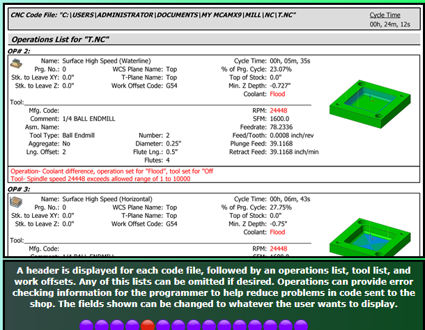
Happy to help. I think you're probably at the same knowledge level I am as far as the Reports Designer goes. I never got past the "just modify an existing one" stage.
Hahaha that's exactly what I have done. It's painfully annoying trying to even get my modifications to go as I'd like. I've thought about trying to convince the boss man to get Varco Reports. I have heard great things about it.
I can see they already have feed/tooth shown

-
3
-
-
19 hours ago, jas6142 said:
Matsuura mam-52v system looks like it it would fit the bill as well. Ill check on availability. Seems like that is the biggest factor that we have been running into.
At my shop we recently dove head first into automation, got a mx-330 pc10 and mam72-52v. I've been running the MX for a few weeks now lights out and I have to say it's been a breeze. Only on the second job on the machine but it's been smooth sailing. I can't compare to a hermle or DMG though; I came from a Haas UMC so this is quite the step up lol
Very soon I'll be starting on the first job for the 52v and I'm quite nervous/excited. Still waiting on fixturing but I was doing some tests inside mastercam/CAMplete for clearance with these schunk WDM 5x modules, it's surprising how little you have to raise your workpiece off of the table for access.
I actually wanted to get 100mm tall modules but sadly they only had 125mm in stock.
(dummy reference part I extruded but general shape is there)

-
1 hour ago, Kalibre said:
A little belzona can give a guy a lot of first chances.
had to google,... never heard of that stuff but that sounds interesting... I'll keep this in mind for future fixturing mess-ups
-
1 hour ago, volitan71 said:
Just talking to another machinist in the company, he suggests putting bushings right in to the table.
I didn't like the idea at first, spent so many years trying to not drill into a table, but the more I think about it I like it.
I like it until one of my operators crashes into something and eggs out one of those holes milled into the table
Personally I would be open to having some locating holes milled directly into tables, but I would much prefer something like a 1" baseplate which locates off of the bushing holes but after you locate and tighten down the subplate, you could remove the bushing/locating pins just to ensure that your precious locating holes don't get fudged up from a crash.. maybe I'm over thinking it lol I tend to do that.
I just designed a few tombstones for new machines and I did something like 12-20 locating pin holes per face just to "cover all my bases" for future subplate designs, and if someone crashes and messes up a locating hole we can swap to an unmolested one haha.
-
20 hours ago, mackenzieruiter said:
Then a test shall be done! I owe everyone at least something for the help I have received.
Should be able to get a few different scenarios put together with some different materials.
keep us posted on your findings

-
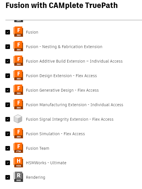
I just got a fresh copy of CAMplete and it seems as though it did come with Fusion, but I did not install it.. (yet??)
I should probably google "what is HSMworks" to start
-
great read!
this was the one that really set it in stone for me:
( I'd start at 2:45:00 LOL )
-
 1
1
-
-
The only thing I ever have really customized was my right click menu,.. other than that I just roll with the defaults. ehh probably not the best choice but it's all good.
-
1
-
-
23 hours ago, SuperHoneyBadger said:
Without permanently hijacking this thread, and while you are here - can you give us the elevator pitch as to the advantage of 3 Axis Deburr over Contour 2D/3D in deburr mode? I have been looking for the major differences and have not seen a post that outlines it. Most of the info seems to be "if you like 5axis deburr, you'll love this" and I don't have multiaxis to know what I'm missing!
I honestly haven't messed with the new 3 axis deburr but multiaxis deburr is IMO a total game changer on a 3axis machine. drop in a nice lollipop cutter and you can get some pretty rad results and a way nicer looking finished product when it's not just some simple orthogonal part.
-
2
-
Using Stock Model As Stock MC24
in Industrial Forum
Posted
I see what you mean. I am pretty sure that is not (yet) possible in mastercam. It is definitely an arduous task and one of the reasons why I dislike rev changes
I have done a decent amount of searching on this topic and have only found the workaround that we both seem to be using. If anyone would know for sure, it'll be @Aaron Eberhard