huskermcdoogle
-
Posts
1,285 -
Joined
-
Last visited
-
Days Won
3
Content Type
Profiles
Forums
Downloads
Store
eMastercam Wiki
Blogs
Gallery
Events
Everything posted by huskermcdoogle
-

Home / Ref. Points Not consistently posting
huskermcdoogle replied to N.Skinner's topic in Industrial Forum
I am seeing issues with approach not showing up when I select it. I can't get a force regenerate to work, repair file won't work. Suggestions? -
Moduleworks dialog seem to be really slow when you press the + button, same for the check button. Takes about 20 seconds to close now. Regen is super slow now too, this is unusable. Grrr. Anyone else experiencing this?
-
Ditto, nothing like walking up to a machine with AICC I that has no parameters setup and trying to do a high speed rotary cut. Sink or swim folks. If we programmers and engineers don't get challenged progress will never be made.
-
Is it possible he has lock on first wcs activated?
-
Rotary move feedrates when using AICC 2.
huskermcdoogle replied to huskermcdoogle's topic in Industrial Forum
Foghorn, I have all of the above, just haven't tried G93 by itself. Can you not use G93 with G43.4 tcp? Husker -
Rotary move feedrates when using AICC 2.
huskermcdoogle replied to huskermcdoogle's topic in Industrial Forum
David, I was playing around with almost exactly this the other night, I had it outputting deg per minute when there was no linear motion, was having trouble, am still having a little trouble understanding what the machine is looking for to achieve the feed rates I program when there is only a minute linear move as well as a rotary. You wouldn't by chance have parameter 1465 set to zero would you? In essance my machine when in turning mode is a 4ax. I can do 5ax cuts with it, but with TCP on 4/5 and no TCP control on 6, the 6 is essentially a dumb old rotary axis, no dynamic offsets, nothing, only for the tilt. Thanks, Husker -
Rotary move feedrates when using AICC 2.
huskermcdoogle replied to huskermcdoogle's topic in Industrial Forum
Fanuc 31i-A5. Well mainly, it seems things are tuned pretty well. Y axis is slow, but there is a lot of mass to move there (gantry). X and Z are quick and the rotary table is very dynamic. Seems to be tuned very well. We can do A Z motion like champ with very good accuracy (IMHO) at reasonable speeds (60-80rpm). Max feed is 43200deg/min. Anyway, B and C are relatively slow, but seem to do well within their limits (9000 deg/min). Main issue I have is I have no point of reference or local mentor to pass things by that can help point me in the right direction. Up til now I have always gotten this stuff, but haven't ever ventured into any simultaneous rotary work. Just toolplane type work. Now that I have my head wrapped around how to do tool axis control and some basic applications of some of the advanced paths like morph, I would like to apply some of that and try to make things run at some level of potential far above where I am at now. I think at this point the biggest thing I need to do is plug in the equation in the book on how to calculate feed when a rotary is involved. That way I can output feedrates that will get me speeds that intended, instead of what I think will work, but is commanded far above the what it will actually go. Mainly I need to calc feeds for deg/min when there is no linear movement. Any suggestions on this subject? Husker -
Rotary move feedrates when using AICC 2.
huskermcdoogle replied to huskermcdoogle's topic in Industrial Forum
I understand the need for an F command on every line with G93. Nope, its a CMS. After reading some more, the need to run in G93 isn't nessesarily required with TCP. However, thinking about it, maybe smoothing, and smooth tcp would be good options to have and would help the situation. My issue is more that I need a way to make sure I get accurate feed when there is only a rotary feed on the rotary table. When there is ample movement of linear axes it doesn't seem to be an issue. Ron any comments? Are you typically using G93 or G94 with Head/Table movement. What about with H/H? or TT? -
Rotary move feedrates when using AICC 2.
huskermcdoogle replied to huskermcdoogle's topic in Industrial Forum
Well I don't have trouble activating G05.1Q1, I get an alarm when I command G93 to switch feed mode. Would this be indicative of not having inverse time feed? Do I need to have inverse time feed? What benefits does it have if I can command feeds fast enough to do the job? -
Rotary move feedrates when using AICC 2.
huskermcdoogle replied to huskermcdoogle's topic in Industrial Forum
Yes, but I wasn't questioning that. I was questioning the command method of feedrates G93/G94 when doing 4th/5th rotary cutting. It seems I can't command G93 when in AICC. Wondering what my options are to get better motion. -
Rotary move feedrates when using AICC 2.
huskermcdoogle replied to huskermcdoogle's topic in Industrial Forum
So this may be an option I don't have and need to purchase? But for some reason don't have on a six-axis (H/H + RT) machine? -
Ok, so this subject has bugged me for a long time. I have not been able to wrap my head around it. Fanuc 31iA Can you run inverse time feed when in AICC II and performing rotary cuts? How do most of you guys handle feed with 4/5ax toolpaths? I am struggling with understanding what I need to fix in my post to get the output that I am looking for feed wise. I have ideas, and know how to achieve it post code wise, just don't know what I need to feed the machine to get the motion that would be smoothest and safest for my cutters. Thanks, Nick
-
Yeah it should work very well, the stepping down method is quite effective, just not as good as a spiral path, hence my desire to pull my head out of my rear. Anyone have any suggestions on how to have it transition into a side cut at the bottom? Though thinking about it the step over might be too much, so two toolpaths would likely be needed. However there may be some cases I can think of in the near future when it would be handy to know how to do this using larger tools. Name of the game is preventing chip outs. (cutting wood)
-
Thinking along these lines, and maybe this can be done ( I am not aware ), but it would be nice if we could define variables, or use tables easily to drive tool path linking parameters, inside Mastercam. Or reference values placed in other operations by standard named variable names.
-
Wasn't too hard. Two circles, one surface. I tried to have it then transition into spiral motion to create a cylinder, but couldn't get a clean transision. Will need to two tool-paths for that, but no big deal. Parting_Motion_Sample.mcam
-
So if I wanted to go this route then I would need to have a lead in and lead out contour path if I wanted a linear lead in and out?
-
That makes perfect sense. I was thinking there might have been a simple way, but my brain wasn't recalling the spiral geo tool. I have never had very good luck with 3 to 5 conversion. I will play with it tomorrow night. As for now, time to hit the road for a few hours. Husker
-
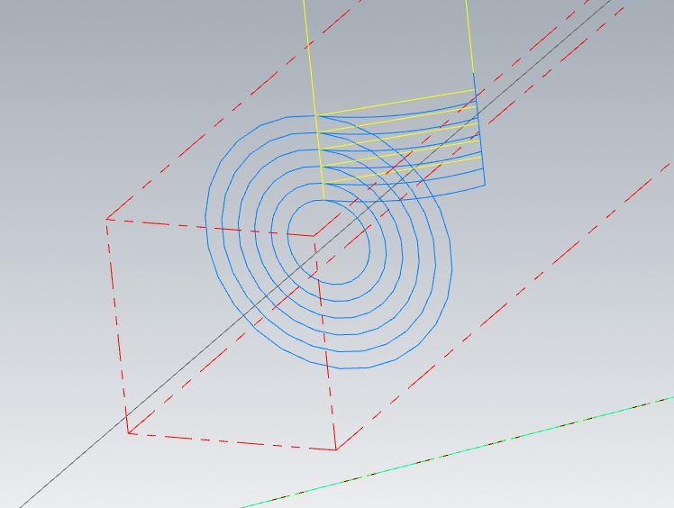
Anyone know off hand a way to spiral inwards with a multiax toolpath. I was thinking Morph, but it won't let me put in 90 for side tilt. I need to start out at say a 40mm and work my way into a 12mm diameter. Keeping the rotary moving while in-feeding in Z. Similar to parting off in a lathe. But instead its a 5ax H/H router with a rotary table axis along X. I am currently stepping my way down using a curve 5ax with depth cuts. Don't like the retract and then lead-in transition from linear to rotary, just seems clumsy. See picture Normally I would have figured something like this out on my own, but my head is in other places at the moment and I am in a crunch to get out of here for the evening so I said, WTH I'll post up and ask if someone has a brilliant idea to share for the next time I can get back to this or need similar deal. I can create a sample file and post up tomorrow if that would help. As usual any help or comments are much appreciated but not required!
-
Multiple people using the same file
huskermcdoogle replied to Brian Pallas's topic in Industrial Forum
This might be a simple c or net hook application for mastercam that one could have all users run upon opening the file. -
I use G41.2/G42.2 regularly with square ended tools for contouring. Very handy, both when doing toolplane paths on a head head machine, for for 5ax contour cuts, certainly makes life easy.
-
I wonder how many people would use it if it was readily known how to use it? More machines shipped these days have lots of options like these turned on, but they aren't taking advantage of what they already have. For example I hadn't known what I had for options until I started comparing the manual to the fanuc data sheet. Turns out making hand edits to things on the fly are pretty darn easy one you start throwing things in there like G68.3 and the lot. I constantly have had the need to just make quick "safe" tweaks to simple drilling routines, or need to make size or blend adjustments due to thermal drift (40-50 degree swing in the shop sometimes). I can't be the only one in that boat. I think it just comes down to education, and knowing how to apply some of these advanced functions on the machine. Thanks for confirming that I am not crazy and missing something, it's much appreciated, I will see about having my re-seller put in an enhancement request.
-
FYI same result with old school multisurf path. Still goes to the pattern surface, not the compensation surface. I don't look at this per say as a bug, just a major limitation in the software that should be addressed, as I am sure many of us would love to be able to use 3d comp with a ball mill on with our 5ax toolpaths. Is it needed all the time? No. But would it help those of us that do production runs with 5ax surfacing? Certainly. I am sure it would be easy for the moduleworks team to give a setting to output to one or the other depending on our needs, they already know the tangent point, it would just be a matter of the transformation of that point and converting it to a unit vector and then writing outputting to the nci accordingly. Of course I simplify that, but all of the framework needed is there, just a matter of manipulating it and outputting it.
-
That's the way I look at it. We will have to see if anyone jumps on this train with us.
-
So I have been looking into adding 3d comp into my multiaxis post. We are talking G41 with IJK vector of compensation on each block, not a g41.x . At least this is what code I believe I need to use.... at this point I am fine with the post modifications to get this done, I believe I can get it done without too much hassle. My issue is mostly with on the Toolpath side of things and the surface normal position. It appears that the surface normal position that is generated will only be on the pattern surface. So, like in most cases of my programs I am using a pattern surface and compensating to other surfaces using collision control in the moduleworks paths, or compensation surfaces in the moduleworks paths. To generate code that will run on the machine efficiently, using a cylindrical pattern surface is about the only choice, this way movement is pretty much forced to one rotary and one linear axis at a time. Adding two linear just adds problems as the whole bridge needs to move. Much much slower and far more violent / hard on the machine think, head/head router with rotary table along x as well. So to finish this thought, I don't believe I can get the surface contact normal for the surfaces I need to compensate to. Might this be a bug, limitation, or is there something that I am missing here? Husker
-
DMG Mori 5 axis DDRT
huskermcdoogle replied to Ewood42's topic in Machining, Tools, Cutting & Probing
Are you not using G68.2? Or at the very least calculating the transformations in the macro itself based on some simple adjustable offsets?