


MotorCityMinion
-
Posts
1,259 -
Joined
-
Last visited
Content Type
Profiles
Forums
Downloads
Store
eMastercam Wiki
Blogs
Gallery
Events
Posts posted by MotorCityMinion
-
-
GMS1, I worked @ Metric right up the street from you. Also worked with Tom Nevel at 2 other shops in the past. The shop I'm currently at just got some of the Mitsubishi mills to try out on some Rex tools steels and the guys were adamant about running traditional speeds and feeds on a Tree mill. (Chickens). They never tried the 90 IPM like the rep said to start out at. I have access to a Makino S series VMC but no decent e-mill holders to use it with. Mostly shrink fit. Maybe I can talk them into buying some new holders for the Makino for a project I'm working on now.
http://www.emastercam.com/ubb/ultimatebb.p...ic;f=1;t=029938
How's business there?
-
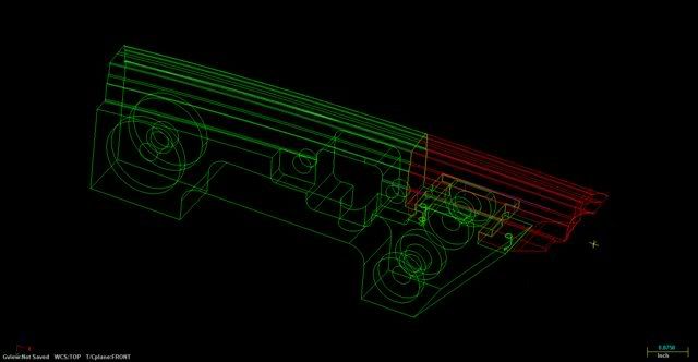
Lots of gaps in this one. I've used find overlap before and very rarely do I get issues with that or actually find overlaps. I'll try the convert to solids. This is a two piece part though and part two (in red) gets wired out of part one. I'll still need to get those splines fixed, then create the surfaces, surface to solid, create curves around all edges. Wish I had a full print.
-
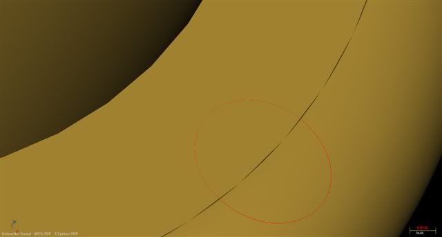
YUp, all the bores your seeing were splines, there arcs now.

-
Version X MR2
Noobish question indeed and I'm in way over my head on this one.
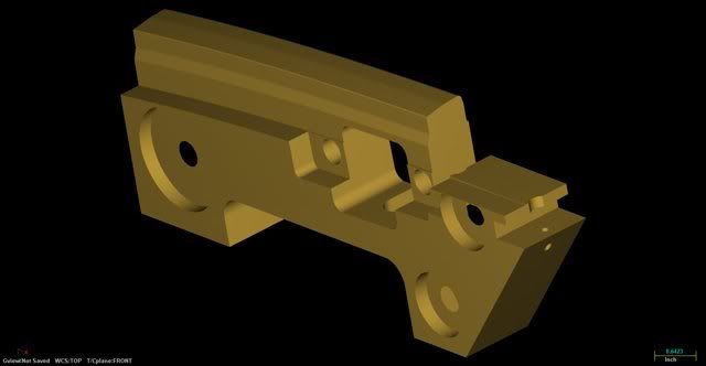
OK, I've got a nasty .IGS with a ton of poorly drawn splines in it. I need to clean this mess up before I start machining it. Heh, print says "Machine to CAD DATA". Not gonna happen. Data is no where near close to holding water and chaining is difficult. I did get quite a few surfaces with the .IGS.
Any thoughts on how to do this?
Is there a way to convert it to a solid, export it, and bring it back and simplify it so I can get some usefull arcs? I've tried breaking up the splines and converting to arcs. That gets ugly quick. I can take some liberties with dimensions, I just can't have gouges and strange rads appearing suddenly on the part.
I'll throw up a pic in the next post.
-
Cobra, .04 FPT? Seriously?
Prosin, 350 IPM? What material?
Both numbers are impressive, assuming were talking about mild steel, for tool steels, those numbers are amazing.
-
Most customers have Quality manuals that repeat these specs as well as other demensional tolerances. Try checking with your QC dept. to get some copies run off, or perhaps a .PDF.
Mil Specs as well, google it.
-
Good tip.
I'll try that also. I'm constantly making pretzels, ribbons , bows, stalactites and so on. I always just kept trying different directions to get it to work.
-
When I hit print, there are NO scaling options in the preview. There are no dialog boxes prompting me for a variable. There are no menus what so ever.
Nothing else in the toolbar, no other menus on that page. I understand WYSWYG. I'm saying this worked before without any thought, zoom in on what you want to print, hit print, done.
-
Alright, now that i'm curious, can someone post a picture of it?
-
No scaling option in the mastercam menu. I'll try the alt f1, or check the printer settings through control panel. Thanks for the tip.
Why can't peeps just leave things be? Both issues worked fine a few weeks ago.
-
Do you mean setting the precision to a smaller value or larger?
-
Version X MR2. MPMASTER
I'm getting redundant Z moves in my arcs, whether it circle milling or contour. They appear right in the middle of the line with the arc moves and equal my depth of cut. Never noticed this before and it looks like somebody messed with some settings somewhere. Any clues?
Off topic. I can't get my printer to print to scale in mastercam. I get 1 page with a few lines in it, Zoomed in on something useless. The only two choices I have in the menu are print preview, and print. No print to scale. This also used to work.
-
Some of the smaller Mazaks are pretty wimpy, although they seem to be more accurate.
H400? That's a mid size horizontal, not even in the same class , or price range.
-
Try putting a magnet over the switch. This worked on older Mazaks.
-
That was fast, you replied before I could actually see my post.
Um, where might "Screen setting resolution " be located? Thanks.
The blue ball setting is at .0002 for the drawings you see. Changed it to .0001 with no effect.
-
Version X
When I create surfaces, I'm getting gaps and flats where the surfaces meet. All the settings I can find have been set at .0002. I used Swept Surface, Flat Boundary, and Surface Extrude to create them, all created on a decent computer. Surface extrude seems to produce the cleanest joints.
How can I reduce or eliminate them?
Do they effect machining accuracy?

-
2 VF3's, 1 VF4, and a mini mill here. I hate the mini mill, the others are great. Buy the Haas and with the saved cash, another puter and seat of MC.
-
Not blanking peeps.
Motor is working in a toll and die shop, (That's right, Toll), although I have done blocks and cylinder head work for many years, primarily on 4 axis horizontals at Paramount and Galaxy. Where you be from?
-
Version X.
How can I delete an entire level from the level manager?
How can I delete a workgroup from the Op's manager?
Off topic. I used "hide entities" to hide some surfaces. When I unhide them, they came back in stretched / extended, even though most of them were never trimmed. Can this be undone?
-
Smiley, I don't think the CRT has anything to do with the speed. If anything, most Lcds have lower refresh rates, which may cause slight visual artifacts, but not necessarily slow it down. Sounds like the video driver should be stripped out, including remnants left in the registry and any folders, then reloaded when switching monitors. You might also want to try using an older driver version for the CRT. I,ve got a 21" HP p1230 CRT side by side with a Acer 22" widescreen. The CRT blows away the flat screen on the refresh rates in the gaming arena, but I don't believe that would effect Cad performance. You gotta love the vibrant colors on the flat screen though.
As far as the mystery P4 goes, we also have one that moves along real nice with a cheap video card in it. I'm using a Intellistation with a core 2, 3gb, Quadro 3400, and it appears to be only marginally faster than the P4 with 1gb of ram in it. I'm gonna reformat the drive on the IBM, strip all the fluff out of the OS, and see if that helps with performance.
-
Yes, fairly generic code used on those controls. The control is easy to learn and simple to use. Not much good for mass editing or on the floor programming though.
-
If you have Home, don't waste your money by upgrading to XP, no real benefit there. If your buying new, then go for XP pro. Doesn't matter whether XP utilizes 2 cores or not, its tough not to buy a new comp that doesn't have 2 cores. Security? Tons of aftermarket apps to help with that. Other than that, read JP's comparison link.
-
Mastercam doesn't have an easy button, nor will it turn you into a machinist. Follow this link and get all the info you need on Milling to get you started.
http://www.kennametal.com/en/support/techn...itories/referen celibrary/en_US/referencelibrary.xml&id=/repositories/referencelibrary/en_US/referencelibrary.xml§ion=support
-
Maybe disabling it in msconfig might work. (Avoiding IT personnel). I'd run just the minimum # of programs for a few days, then turn them back on 1 at a time, wait a few days and repeat. That might help you find the culprit then apply some tweaks. UG, MC and and explorer twice with outlook, sounds like your pushing that system.
Spline to arc conversions.
in Industrial Forum
Posted
No luck so far. Turned the WF into a solid, created the curves, deleted the solid and was left with about 1/4 of the lines I needed. I might try this with Rhino and see whats happens. I'll keep messin with it in MC for a bit.