


MotorCityMinion
-
Posts
1,259 -
Joined
-
Last visited
Content Type
Profiles
Forums
Downloads
Store
eMastercam Wiki
Blogs
Gallery
Events
Posts posted by MotorCityMinion
-
-
-.-
I don't consider myself sloppy, or a poor planner. I have programmed many parts from home, with a cold one in front of me. Funny how the numbers stay the same when I take the program into work, despite what some people claim here.
One work offset for the entire part (rotory table), regardless of the number of faces, or number of parts. Try and set your parts at a nice round number away from the cl of rot. If you set your working suface at A0. to Z+10., X+5., it becomes X-10., Z+5. when rotated 90. deg.
-
Version X
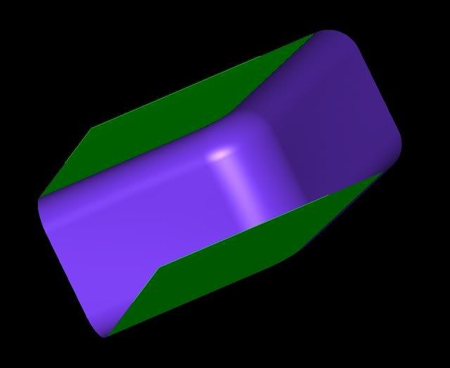
Two problems with this surface.
The first is that it wont size out when I post the g-code. The distance across the green surfaces is 1.215, and symmetrical about the Y axis. I'm using a .50 bullnose with a .125 rad. It should post with y +/- .3575, but I'm checking my extents and seeing .3486? Stock left on drive surfaces is set to zero. Max step over is set to .01, tangential line length set to .25. Corner rads are .25 and .50 in the pocket.
Second issue. With depth limits set to -2.28 max, I'm seeing -2.2841 at every approach, and a bunch of x/z taper moves across the bottom. The lower left corner of the pocket starts at X3.4085, Z-2.28, and the .50 rad starts at X4.8184,Z-2.28 on the actual part. The bottom of the pocket is flat. GRRR. Here is the code I'm getting:
Could the net surfaces be out of alignment with the wire frame geometry?
N985 G00 Z.2443
N990 Z1.
N995 X3.0326 Y0.
N1000 Z-2.1841
N1005 G01 Z-2.2841
N1010 X3.2825 Z-2.28
N1015 X3.4585 Z-2.2771
N1020 X3.641 Z-2.2746
N1025 X3.8351 Z-2.2726
N1030 X4.0556 Z-2.2714
N1035 X4.3118
N1040 X4.5528 Z-2.2726
N1045 X4.7597 Z-2.2755
N1050 X4.7631 Z-2.275
N1055 X4.7817 Z-2.2714
N1060 X4.8006 Z-2.2669
N1065 X4.8195 Z-2.2614
N1070 X4.8384 Z-2.255
Close, and looks good machined, but still wrong. Any clues?
Thanks for your help.
-
The vegetable base stuff is expensive and builds up in every nook & cranny in the machine, and takes forever to clean out of the machine. Think of a can of bacon fat solidified. Ya, it does stink to high heaven if it doesn't get churned everyday. Blaser does make an awesome product though.
-
Just curious. I work primarily with .IGS files and have not had any problems with them so I guess that what I don't know, won't hurt me. What are the benefits of X_T and step files? The parasolids actually create more work for me, as I end up stripping out 3D geometry just to clarify the views and make chaining easier. Should I be converting the .IGS to x-t or step? I'm thinking that might be redundant or even mess up the drawing accuracy. Thoughts anyone?
-
You tell em' Apps guy!
-
Try the settings/parameters page at the Haas to turn features on and off. Our vf3's and vf4's read A0. no problem, even though there is no rotary axis on the machine. MPMASTER blows away the generic Haas post, but both work fine. I turn the A axis off in Mastercam.
-
Flame suit on.
What do you do when;
the fixture gets reworked? MCM: re-work it properly.
the job gets run on a different machine? MCM: Post to the new machine
the material came in undersized but is still usable with an offset change (due date in two days)? MCM: Issue a NCR to purchasing then grab some shims.
the material was cut crooked so you need to clamp 1/4" max to keep the part from "squaring" itself.? MCM: Change saw blades.
Nubs. Centerline of rotation is the same on any machine, which BTW, does in fact allow a programmer to program from the pub across the street. If your operators can actually put a fixture where it belongs, it will work on any machine, just change the post. Of course I'm talking about programming real work, with multiple planes on it in increments other than 45. and 90. deg, not the rough sawn raw material that any noob could run on a Bridgeport.
Did I make it through the interview?
Time for a brew. Join me across the street before the center of this pub starts to rotate.
-
Turn on the restart feature in the parameters. Cursor to the point in the program where you want to start machining. Turn it off after the tool finishes or weird moves take place when the next tool starts.
-
Larry, there is a HUGE advantage to working this way. No reprogramming and no trig work the next time you run the job. Also, tool lengths, relative to the spindle nose and in set-up sheets remain the same if you place the part in the same location at every run. If your running multiple pallets, it gets even easier when you locate off center of rot. A lot of peeps have trouble grasping this concept if it's there 1st time around with horizontals. Heh, some never do, and others can't even rotate the part other than in 90. deg. increments.
-
140sfm /.0015 per tooth in mild steel. 300sfm / .003 for aluminium. This worked on a single point tool, (6 teeth on the same plane though, carbide tool from Micro 100), going 2.65 dp. Had to offset the dia. in mild steel quite a bit .
-
I've milled .04 thick glass fabric using a sacrificial piece of stock and toe clamps. I was able to mill .02 off the top, and bury the e-mill on the profile, maintaining a .002 tolerance. Leave a tang on one end, mill as much of the profile as you can. Use can use the e-mill to punch holes as well. M00, put a clamp on the finished side, remove the other clamp from the tang, then mill off the tang. Clamps for lathe inserts work good for this if you have some lying around. Use a penny (stone or sand it so it doesn't leave marks, or a chip breaker to spread out the clamping forces. Use a stone on the part in between moving clamps to give it a brushed looking finished. You could also get creative with a small e-mill to finish the surface with swirls, curves, diagonal lines,and so on.
[ 02-26-2008, 12:58 PM: Message edited by: MotorCityMinion ]
-
Head the fire warnings. I caught a lathe bed full of mag chips on fire. Somebody used the lathe and didn't clean out the chips. It went up very, very fast. Cleared out half the shop in under 2 minutes after I let loose with the fire extinguisher. Don't play with it or "show your kids". Before you know it , they'll be trying to light every piece of metal on fire.
-
A killer card in an older PC may also be overkill.
That 3700 looks like a good choice for speed. Not knowing the prices makes the choice tough though. The Quadro's are not cheap by any means. If financial resources are limited, the retail cards for gamers might be a better option. 8800 GT perhaps?
-
Dude,
quote:
--------------------------------------------------------------------------------
11. Issues with your reseller should be resolved directly with your reseller and/or CNC Software. Airing out your issues using the forum will not be tolerated.
--------------------------------------------------------------------------------
FAQ
I would kindly ask you to please refrain from your issues with your reseller.
MCM: Both positive and negative issues?
Heh I knew that would irk somebody. Take all the training you want. All I'm saying is that, get you're feet wet first. Get up and running, make some parts and spend the profits on the reseller training when you can understand and absorb what they are teaching. You'll be able to retain and put to use more of that training in this way.
-
I agree, don't spend money on reseller training, too much info too fast, and costly. Get some videos/books and contact someone that can come to your facility and deal with your needs in house. I do one offs all the time, so the learning process takes off fairly quickly, plus you already have one of the finest resources, this forum.
-
Can ya save that file as an X version, not X2?
-
I quit a job after 7 1/2 years because they were adamant that I start programming in Mazatrol instead of EIA. The company was in the process of reviewing different cam packages, everything looked Greek to them, and they're still looking for programmers/set-up people today. There's no doubt about it, when it comes to machining a lot of holes on multiple planes with different tools, Mazatrol shines. (We machined alot of engine blocks, heads, and other similar castings. Mazatrol milling, IMHO, SUX. Mazatrol is also a good system for new machinist with no g-code background. You can get up and running fairly quickly. After using Mazaks for almost 13 years, I can honestly say I don't miss em'.
I would not call the transition easy though. Consider it bad medicine. In the long run, you'll be using MC on different machines and increasing your flexibility.
-
Found this, and it also works good.
Ocean Lacky
Senior Member
Member # 10728
posted 06-27-2007 09:51AM
--------------------------------------------------------------------------------
quote:
--------------------------------------------------------------------------------
"can not extend trimmed surface"
--------------------------------------------------------------------------------
Try the 'Extend Trimmed Surface Edges' function. It won't alter your original surface, but creates a new surface adjacent to the edge of the selected surface. Really handy for just this sort of thing.
-
If that doesn't work, I'll try to figure out how / where to upload it on the fpt. You should be getting it twice, I mailed one out this morning. I work afternoons so after 3:00 I'm usually off line. Just didn't want you to think I was ignoring you.
-
Oops. That pitch description should have read .125 of pitch. Actual full pitch is .896.
The .bmp that Paint creats realy mucks up the images. .JPG was worse. What apps are you guys using for image editing that retains the image quality as seen in mastercam?
-
On it's way.
-
Yup. Sit tight, gotta switch PC's.
-
I tried your suggestion Bosto. Default was .002. Switched it to .0002, .0001, and .01, restarting MC everytime with the same results. Changing tool step over doesn't help much with the machining either.
Mayby the viewing angle is distorting the edges.
Looks like I'm being too picky here. I redrew the helix with different rads and used a .236 bullnose with a .02 rad and cleaned it up with a 3/16 flat e-mill.

-
Thanks for the help. Learned a lot from the answers but I've also opened up a can of worms. OK, here's what I've tried so far.
FYI: The helix depth is only .112", .197 inner R, .3525 outer R., .125 pitch.
With tangential line length, positive value is set to radius of the cutter. I get the start and exit points I want. But regardless of the tool type, whether it be a bullnose with a .02 rad., .156 ballnose, or a 3/16 flat e-mill, I get gouging at the bottom or too deep of a cut, even with depth limits set, relative to tip. Looks like I need to set up some type of boundaries?
With the ball nose and bull nose tools, I get "notched geometry at the top of the cut as well. Flat e-mills look fine.
The .156 ballnose e-mill I used refuses to take the inputted step over and ends up only taking about 25 passes. I suspect that its simply too large to fit through the smaller radius of the helix comfortably. A smaller ball would probably work better.
Adding a second tool and then setting the depth limits worked great, kind of like re-machining to get the rad out.
When I created the underlying helix geometry, I only used four lines to define the helix. I was pleased with the results. I then created a net surface. The net surface appears to have kinks or bends in it that, although small in size, appear to not touch the wireframe geometry in several places. Kind of looks like flats when you zoom in. This also shows up in the cuts. Do I need a different type of surface here, other than net, or is this just a visual anomaly?
I'll redraw the helix wide enough to accomodate a 6mm bullnose with a .02 rad, then use a 3/16 flat e-mill to pick out the rad.
Bet ya can't say "tangential line length" 5 times really fast with a mouth full of crackers.
I'll check back in later. Thanks again, MCM.
windows xp home or pro?
in Industrial Forum
Posted
Running a duel core AMD on home now. Cruising along fine.