


kool
-
Posts
73 -
Joined
-
Last visited
Content Type
Profiles
Forums
Downloads
Store
eMastercam Wiki
Blogs
Gallery
Events
Posts posted by kool
-
-
I found work around for that problem for now. I put my outer diameter = (2x corner rad) + tip diameter. put shank diameter to actual tool diameter. keep shoulder length +.001 greater than cutting length.
but then again most rad mill tools have rad center sits below tip +.005. and there is no way to do that unless you build custom tool or cheat.
I found another issue with this new tool building manager. Reamer!!!
Shank diameter and chamfer distance do not stick when you build a reamer. No matter what you put in there. you always come back to find a different value.
-
Are running X7 or X7 MU2.
MU2 seems to be little faster and better in graphics.
-
for Master cam X7,
Is there a way to out put multi axis circle mill tool path as arc ( I , j , k or r ) instead of xy xy xy and turn cutter comp on/off ?
Thanks in advance,
Kul
-
Going for the first time
-
try closing mastercam event log file on task bar startup menu. then try to close mastercam itself.
-
do you have rapid definitions set properly in the Rapids page of the Control Def
My rapid setting in control definition seems to be right(dog leg rapid). Master cam simulate that as it should be for milling tool paths only, but in drilling tool path it moves in straight line from one point to another. if my setting were wrong then it would do that for all tool paths type.
I don't know what I m missing.
-
Just came across issue with dogleg rapids move for drilling cycles in X7 verify.
It looks to me when you are drilling multiple holes in one drilling operation, X7 verify does not show dogleg moves between those holes.
I see that in drilling only.
Is that a true for others, Please confirm!
-
Just came across little issue with dogleg rapids move for drilling cycles in X7 verify.
It looks to me when you are drilling multiple holes in one drilling operation, X7 verify does not show dogleg moves between those holes.
I see that in drilling only.
Is that a bug, Please confirm!
-
This is how I m doing it on 2 Haas TR310.
write you center of rotation for each machine (x,y,z) in custom macro variables (#501, #502, #503). you can pick any variable that are not use by any other program.
Load center of rotation using a G10 line on top of program and call these variable (G10 L2 P1 X#501 Y#502 Z#503) etc.
You can use the same program on both machine using this method.
-
Thanks guys,
Looks like I m rolling for now. I m sure I will have a lot of questions with all the new feature in X7 (tool manger and new verify)
-
I do not use holders on those tools in X6.
I went ahead and said yes to removing those tools, but none was removed from the program.
saved it and reopen the X7 file without any error messages.
but still like to know if it s ok to do
Thank you
-
Just start using X7.
Getting this error when I m opening any X6 program in X7.
Tool Corruption Detection!
Remove corrupted Tools?
Any idea what is causing that and how to fix it without removing those tools?
Thanks in advance for any help.

-
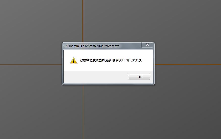
Just download and install X7 sp2 from Master Cam. I was hoping all the BUGS would have been fixed by now since its SP2.
I m getting this message in Chinese every time I open X7.
Is that a new feature in X7 that they forget to mention in "what s new in X7"
Is any body knows how to disable this feature.


-
use MPRouter post with your current machine def. Right angle head is supported in router post.
-
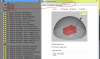
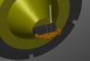
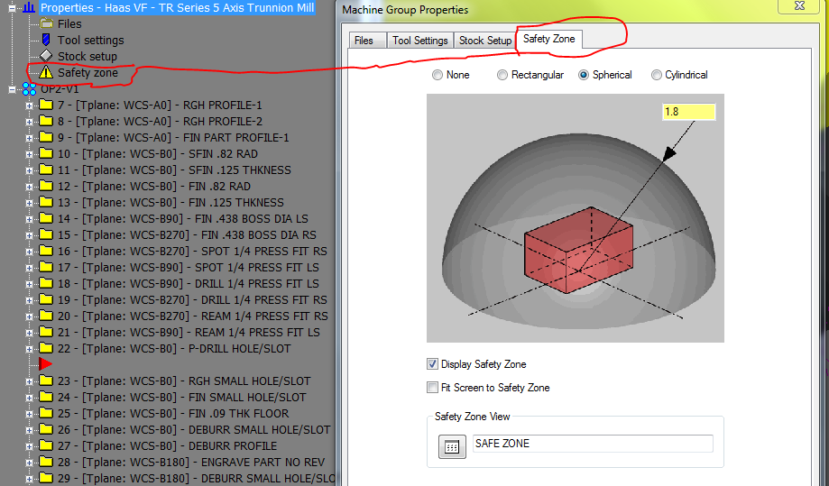
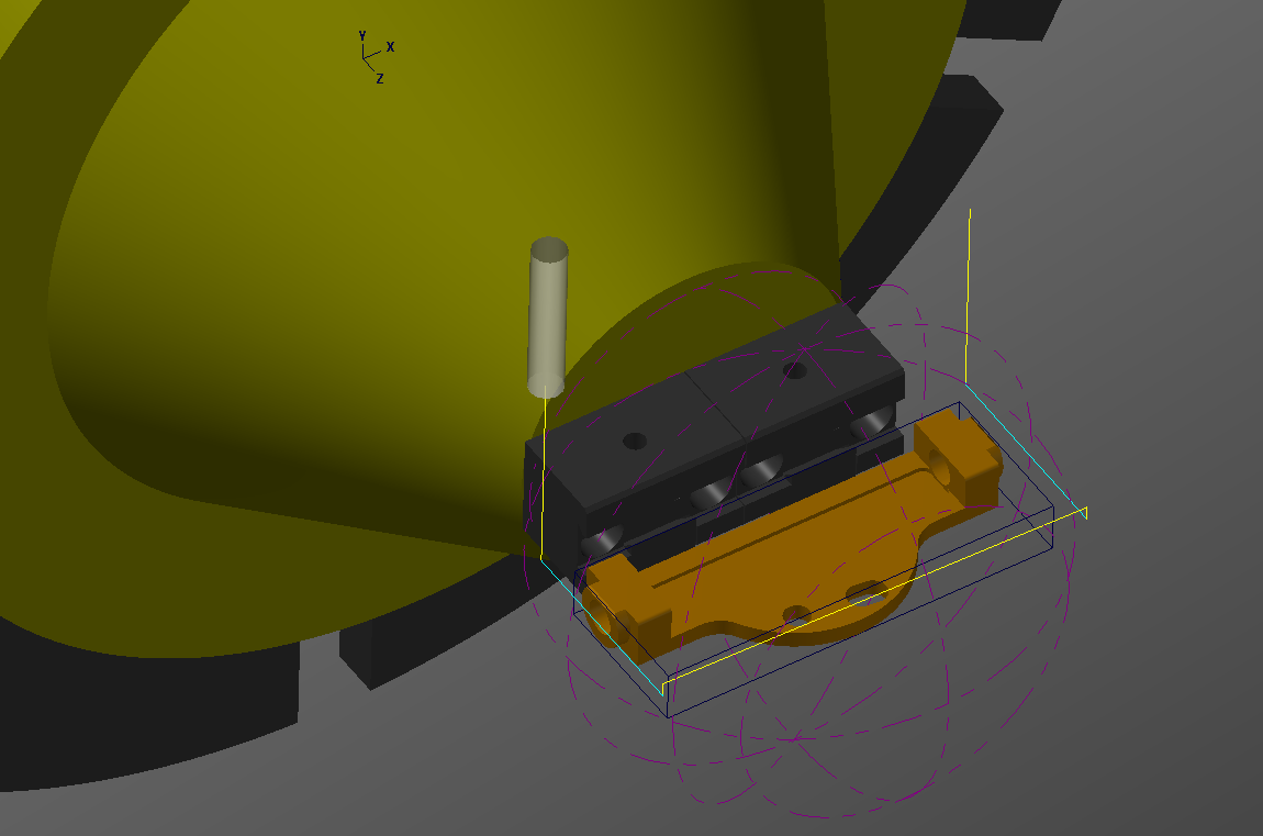
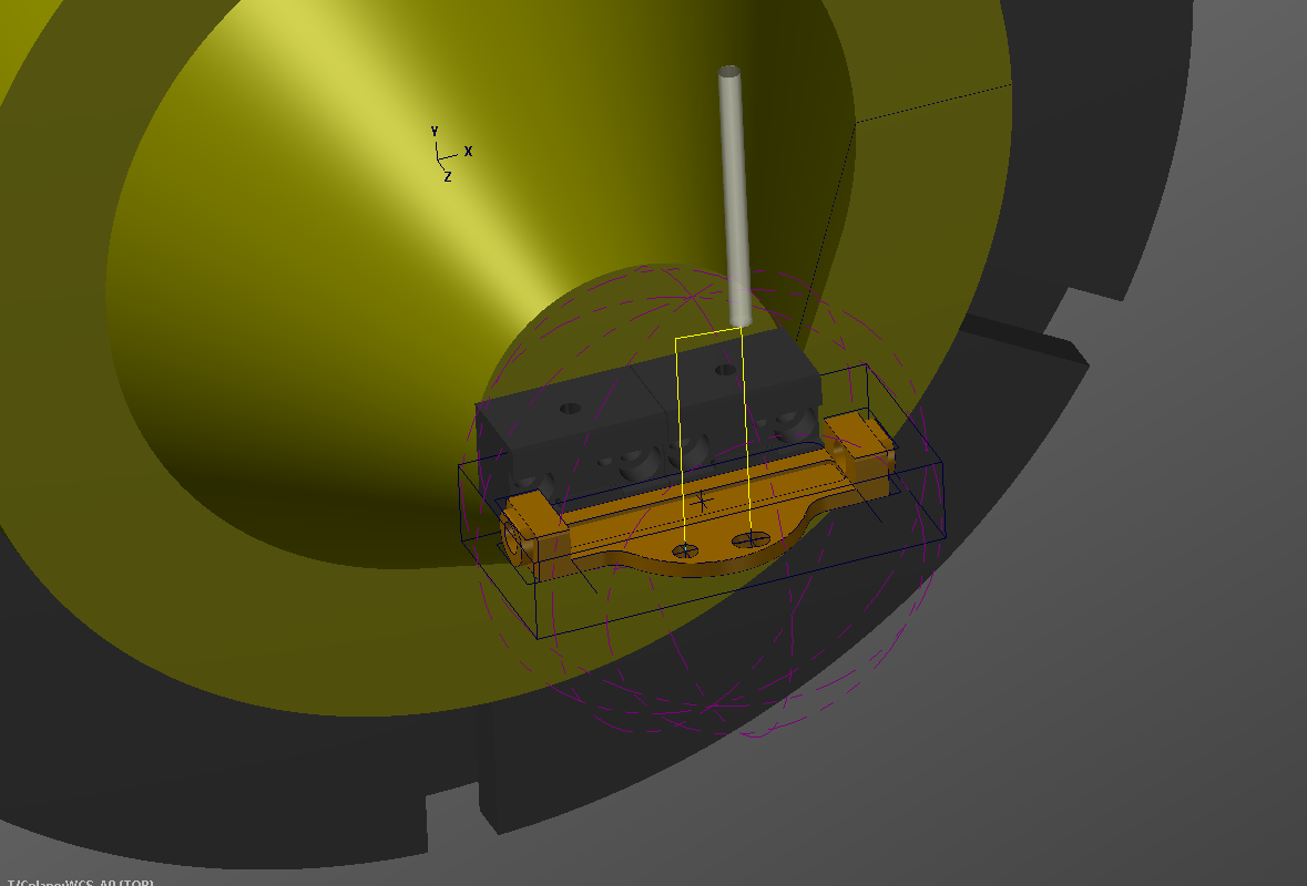
I have recently start using safety zone around a part for clearance in 3+2 axis indexing work. Please see the pic-1 below. I kind of like it in the begining, but then as always I start seeing Bugs in this nice feature.
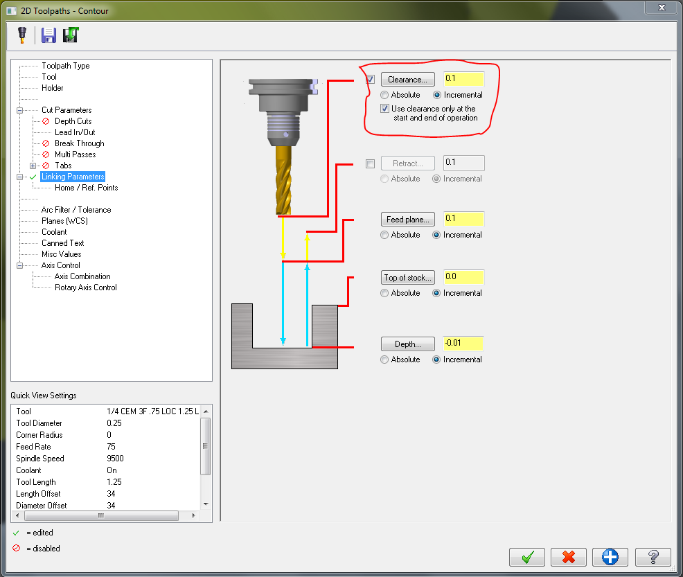
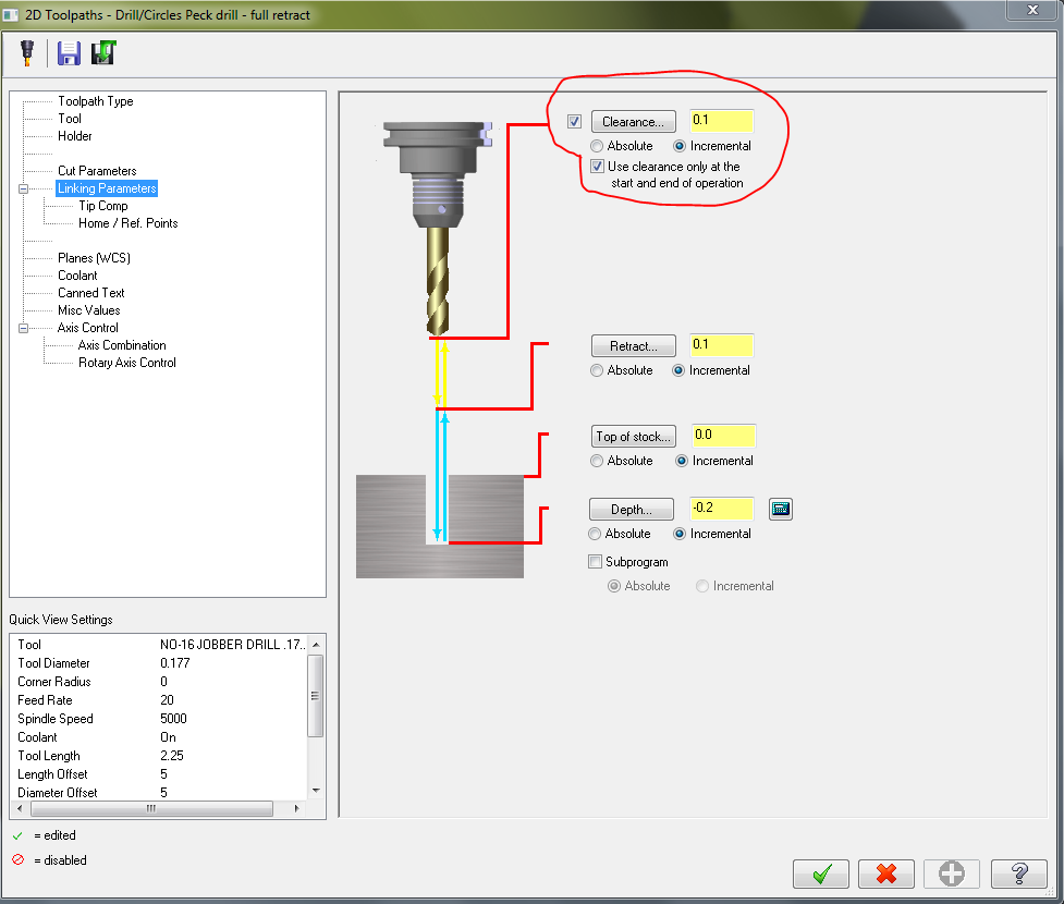
It just does not work same in drilling operation as in Milling operation. In drilling I just can not keep my tool down when I use safety zone. After every hole it keep retracting to safe zone. On other hand in milling operation it use safe zone only at the begining and end of a operation.
Also when I changed my safety zone it do not update my operation automaticilly. I have to regen all my operation even though it is not dirty
Is there any way to keep drill down to feed plane when drilling multiple hole and retract to safe zone only in start and end of operation?
Please help!
-
If you write a macro to calculate the rotated distances in the machines, you can set up your part to use top WCS, move your Tool planes to get the correct rotations, and use your G10 values from Mastercam in your calculations. That is how we do it, except we have Okuma mills. Then you pull in the different values for your stack ups into the macro. I have this on 7 machines with 4 different controls without issues.
Kyle,
Rotation Macro is what we do on our horizontal cell line here. we use one workoffset (G54....) for all the rotations, call the G10 line and G65 Macro line with every tool change or Rotation to calculate -x- and -z- and load those in the same work offsets. I can set my orign at any corner of the stock and this macro can calculate that location in diffrent tool plane from machine zero. But that is only one Axis rotation.
you think I could use the same Macro for 3+2 axis. where you setting you origin (-x-y-z-) for diffrent toolplane rotation.
I think that is little to much with using the one workoffset and calling the G10 and Macro with every rotation. Setup person can not make any adjusment if they need to so Machine stroke has to be really dialed in.
-
Hello All,
I have done little 3+2 programing. Most of my experrance is on horizontal. I just started a new job and my new company just got 2 new 5 axis haas Trunion, so I want to learn more about 3+2 programing methods.
I been using center of rotation for all work offsets and draw my part in space as it is in machine. Set my WCS as top for all operation and move my Tool plane around. Keep all my Tool Plane orign at the center of rotation. Put your center of rotaion in G10 and off you go. But with this method if I use diffrent machine or fixture stack up, I have to move my part in mastercam and then repost it.
Is there any other method that can be used to program? Like instead of using the center of rotation for Tool Plane orign, Pick a corner on stock for orign at A0/B0. and let machine or mastercam find the part in diffrent rotation. That way if your are setting that part on diffrent machine with diffrent fixture stack up, operator can pick that corner for orign. I know some 5 axis machine have an option to compenste for center of ratation, I don't know what its called.
Please Share your thought and guide me into the right direction.
Thanks in advance.
-
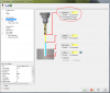
here is diffrance
-
Thank you all.
Thad
Screen-Regenrate display list does the trick.
This was one of those tool bar, I always wonder when to use it. Now I know
-
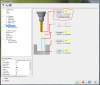
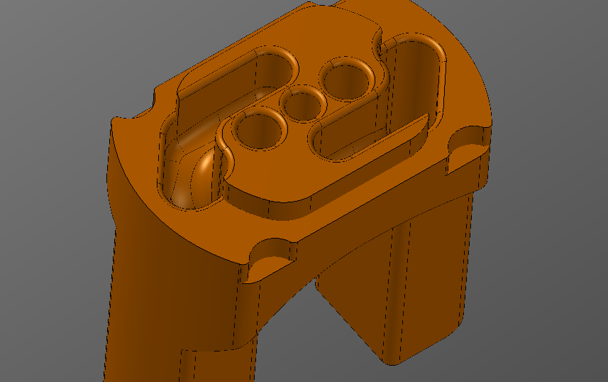
here is the pic of what i m getting
-
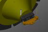
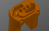
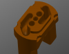
I have this igs file from customer. I trying to import it into mastercam, but it is not coming in right. Fillets and edzes are kind of broken or open. this is not a big part, only 3/8 in dia, and those holes and slots are close to 1/32. I have tried every single method that i know to import, as step, as solid, as trimed surface, as parsolid, as pro-e, nothing is working. if i open customer file in solid work or pro-e it looks fine. only mastercam have some issuse importing it right.
Any body knows any work aroud, please feel free to add
-
Happy Friday All
.gif)
Need little help with Doc file. In operation manager under right click menu there is Doc file option. it gives you a nice text list of all the information in operation manager. Do any body know what .PST file or .set file Master Cam X6 is using to generate that text document.
I know setup sheet is using mill.set file. Thanks in Advance
-
Are they doing it for the ability to name the toolpath group with details about the gage lengths, and diameters of the tool. I currently do this with the tool definition and it can also be done in the tooltable, which gets posted out with the codee. This is how I do mine:
This is how i used to do. Other programmer here used to use Geo Path.Geo Path is design to group operations by tool number and name. In Geo Path, when you make a cut, it ask you what tool you want to use, you pick a tool from a list and it will add that cut under that tool.
Since they are used to of looking at the tool number, they want to use Mater Cam as Geo Path. and now on the name of standardization, they want me to do the same. and i find it really difficult and unnecessary. i don't know how to convince them that Master Cam tool-path group are not design to work as their Geo Path.
-
 1
1
-
-
That seems odd what if you are using that tool in multi operations through out the program you know have to have the same tool group just used #1 and then used #2 and other things. I have done it that way, but it was a pretty straight forward job. For what you are doing yes to me it seems like a lot of extra work.
yes we are adding -1, -2 and so on for all tools. it is not just extra work, it disturb your rythem.i always think master cam is a feature or chain base software. where you focus on one feature or chain not the tool. that is why when you add a cut it ask you to pick chain not tool. unlike Geo path ask you to pick tool first.


Issues with 8
in Industrial Forum
Posted
Now you have to right click, then drag and drop points to another toolpaths to replace them. In older version it was left click, then drag and drop.