


motor-vater
-
Posts
379 -
Joined
-
Last visited
-
Days Won
4
Content Type
Profiles
Forums
Downloads
Store
eMastercam Wiki
Blogs
Gallery
Events
Posts posted by motor-vater
-
-
With stuff like that cant u just post from top, Then write yourself a drill cycle at 90 so it uses G68.2. Use that drill cycle to indicate your feature, adjust your work offset at the control and let er rip? at 90 X outage will be used to adjust Z of your work offset. Or what ever your machine kinematics are. Been a while since I had to lie to the control but always worked for me.
-
 1
1
-
-
Are you asking that if you set A/B90 as zero at the control can Mastercam produce working code that recognizes that its at zero not 90? an example could gain you more of a response
-
1
-
-
I believe Sanvick makes a flatbottom series for 4 axis floor finishing, I have also used Harvey counterbore tools with success in 4 axis operations to cut a floor
https://www.harveytool.com/products/counterbores---flat-bottom
-
 1
1
-
1
-
-
33 minutes ago, JB7280 said:
I was looking at some new endmills Helical has when they combine an HEM chip-breaker style endmill, with a high-feed geometry at the tip, and it made me think of this method you mentioned. Seems like it would be great if Optirough/rest toolpaths had the option to set different speeds/feeds/stepover for step-down vs step-up.
I saw those to and made me wonder, but I will wait for someone else to be the guinni pig. Still seems an expensive option for high feed compaired to inserts but some machines dont hold alot of tools so there is that..
-
we name tools to match our toll crib software
1/2 3FLT EMC .060RAD 1.0LOC IMCO 61047
Makes it easy for tool crib to set up the tool. We follow it up with a basic set up sheet to define holder, extensions and gage length
-
I like IMCO or Helical, but lets be honest its Aluminum. As long as you have coolant it would be hard to mess up with any good 3 flt...
-
3
-
 1
1
-
-
9 hours ago, So not a Guru said:
No, in non-canned cycles the rapids respect what the control switch is set to. It is only during canned cycle rapids, such as moving to or from a G98 clearance height to the "R" height, or the moves between pecks, that the switch's settings are ignored.
Oh I get it, Yes can cycles tend to override things, some for good reason, think tapping. Probably a parameter you can turn off but why?
-
1
-
-
Part of the beauty of buying a Postability post is the amount of support you get, They tweaked ours multiple times tell we got the exact output we were looking for. Email them...
-
The things that could be said on this topic!!!! But yes they have a Monopoly, I have a great relationship with my reseller, but it took years of work to develop a good repour. Best of luck..
-
On 12/14/2021 at 8:50 AM, Aaron Eberhard said:
Great feedback as always, thanks for the discussion!
To answer the questions this is a smaller job shop for now, and I'm trying to ease them into ERP. Whatever I do has to be super simple to get the other guys to actually use it (to Ron's point). ProShop has been on my radar, as well as WinTool. I hadn't heard of TMS. that's a good lead, but it'll probably be out of budget if you can't afford it, Tom.gif ":)")
Thanks again everyone, I'll keep researching and update this if I come up with a simpler solution. This seems like something that would be very easy to dismissively hand-wave away with "Just do X!" and then later be upset that it doesn't do "YZ". Or cause a huge headache when you port it to a solution that does do YZ.Not a good idea to ease into a tool crib management system, We tried it and failed miserably, to many people walking in and out grabbing tools, taking spares, over riding the system and what we ended up with was a tool bill that was double our usual monthly! As others have mentioned best bet is a tool vending/drawer system that can be provided by your supplier, inventory everything you plan on using set min and max and lock that baby down. Its a one man job, and has to be that way! On the back side standardize what you are using, create tool libraries and always try to find a way to use those tools. At the end of the day a well balanced system can save you money, you will rarely be holding tools that you do not need, our vender sees what we are using most and keeps stock at the local warehouse, so we can keep our min max low but get tools same day.
Your the boss now buddy, don't flirt with anything, make a decision and then pull off the Band-Aid, We use the the FTS system from Western Tool, its only as good as the person implementing it, but that being said after 6 months we got it down to a science.
Integration into Mastercam? Come on Man, you are one of us now, you should know better.... LOL
-
2
-
-
Depending on what you are looking for AB tool, And or Xceliron. Randy at Xceliron is the man he has helped me get to some of the craziest precision custom tools you could dream of. And he loves the challenge!!!!
-
1
-
-
check to see if tool holder collision is on, sometimes that can mess with it. Also check steep shallow settings, and finally check the skip pockets as mentioned, with the combination of the min radius settings in cut parameters. Maybe it does not think the tool fits....
Some times I will turn off the stock just to insure its doing what I want before converting to a rest rough operation..... And sometimes I create a whole new toolpath with all the same settings and that works, not sure why but some toolpaths just get hung up on something and a good old fashion restart of the system and fresh toolpath seem to solve the problem.... Thats all I got without actually seeing it-
1
-
-
7 hours ago, Colin Gilchrist said:
Dude, check Parameter #5006.6 !!!
Bit 6 of 5006, tells the machine to "move" the distance of the TLO when G49 is read, if the value is "0". Set #5006.6 = 1. This tells the control to update the display with the current machine position, without physical motion.
This is the first Parameter setting I check when working on any Fanuc control!
If it is set to 1, then you get TLO cancelled without machine motion.
I really can't figure out when this would ever be useful to have it set to '0'.
Yes, I might have got that from u in the past, cause it sounds familiar. My problem was the old post would spit out g49's without a g43 after, so it was the Z motion that was called after the g49 that would try to kill the machine, not the TLO call in its self.. Postability was the best money I spent around here... No more wonkie problems like that...
-
2
-
-
1 hour ago, savagkd said:
I'd also add, wherever possible, use 3+2 and pay close attention to your transition between operations. Most of my problems have happened on the rapid repositions. Verification software is a must!!! Vericut has saved my bacon on several occasions.
Agreed!!! Also if you dont have verification software forced tool changes are like training wheels in 5 axis. Starts from home every toolpath. 5 axis in mastercam seems all good and ez when in verify, but actually verifying G code is a God send, the post plays a significant roll. A misplaced G49 for example will have you polishing up the old resume!!!!!!
-
1 hour ago, crazy^millman said:
Exactly why I will use the 5 axis toolpath where they handle this much better and with more intelligence in the process of making the toolpath. The gap settings play a big part of this in the HST toolpaths, but the fact I can control the 1st and last moves in and out separately from the whole area being machined is huge difference between the thought process of handling situations like this that Moduelworks put into it that HST still has some catching up to do.
I do as well. I almost always do. I am loving unified locked in 3 axis!!!!!
-
1
-
-
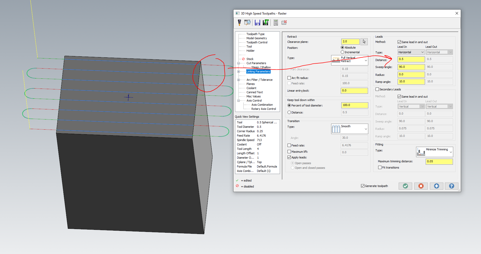
16 hours ago, Chally72 said:
I can understand the confusion, as in 2021 this was explicitly called "Extension", and in 2022 it seemed to disappear. It's simply built into the intelligence of the Leads section of Linking these days. The Distance field is a tangential extension applied before any other part of the lead. Here's an example of what an extension would look like in 2022:
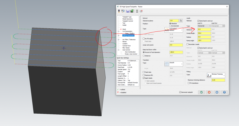
I have a love hate relationship with this. I love what it does, until you add vertical or horizontal radius. Some times I want a controlled lead in/out and I want to extend my overlap. 2 very different things trapped under the same setting..
-
If you do this does this essentially make Mastercam portable? If so that would be cool, But otherwise I'm not seeing the point?
-
1 hour ago, So not a Guru said:
I never noticed this before. What exactly does it do?
IT CALCULATES THE RADIAL CHIP THINNING FOR YOU. A lot of the high end tool manufactures give u recommendations with RCTF already built into the recipe, but I like the little button. If you change step over, it changes feed rate as you do it. Play with it and see what I'm talking about.
But I'm apparently a Sissy so there is that... LOL in my defense most of the machines I run and the window size I work in, the machine would never reach those feeds. I have programmed many aluminum parts and ran it at 100 200 and 500 ipm, and seen no reduction in cycle time "at the machine" from 200 to 500. It just can never get there on small moves. Ive always felt most of us are just lying to ourselves when we try to program those feeds. But without a doubt their are plenty of machines out there capable Ive just never had one...
-
1 hour ago, huskermcdoogle said:
You are way too slow for that radial engagement.
Not that I want to help a competitor sell tools... I would do as follows. If this is in a 50 Taper with a good setup, run full depth by all means. If this is a 40 taper, you have too many points of contact for full depth. But if you back it down to 1.625" depth or less, but not less than 1", you will find success.
Keep the 5% stepover for now.
I'd run 1000SFM, .0112fpt. This takes into account chip thinning and speed factor based on the light radial.
5093 RPM, 341 IPM. Feel free to back off the feed a little bit if the machine can't keep up, but I would go no slower on the feed than about 200. If it burns up try to maintain the chipload, but reduce the surface footage. Air blast would be better than coolant, but coolant would be ok if you can't get the chips away from the cutter. I'd prefer dry if you don't have a chip evacuation issue. A little heat will help you as long as you aren't re-cutting chips.
I would consider the above parameters middle of the road for our tools. The fact that you have chatter is likely a function of machine stiffness. Your original parameters show 6 points of contact, which IMHO for almost any 40 taper is way way too much. 3-4 points is better and should work on even on a medium quality machine
Nothing wrong with 4 or 5xd in steel. Many people do it everyday. But quality holders, setups and machines become very important very fast. As I mentioned earlier, I likely wouldn't be doing that in a 40 taper with a 3/4" tool. If you needed to, I would use a tool with a tapered core and maybe drop a flute or two to keep the contact points / force down.
My favorite 5xd tool is the Kennametal Harvi II long. Never had trouble getting it to work. I've run it in anything from alloy steel to Inconel with very good results. One notable success was in Inconel 718, similar depths to what you are doing now, in a 40 taper, taking about .010 stepover. We had a little springing, but that was from the setup as we were cutting on a weak trunnion table.
Husker
OP please report back after trying this, I would love be get some feed back, I feel like I need some Midal and a maxi pad after hearing Huskers input..... Let that baby eat!!!!
-
1
-
-
I make cuts like that often, but the sfm seems highand there are multiple things to consider, first your holder, I would use a hydraulic then a shrink fit, never a Weldon. They recommend the high chip load because the radial depth of cut is so light. So it takes into account Radial chip thinning.. That being said. I would still start some where around 360 sfm, chip load I would just set it at .002 or .003 and turn on the chip thinning option in your tool tab (RCTF).
Next in your cut parameters you want to make sure you are not forcing this the tool into tight spots, you do that by setting your minimum toolpath radius to like 15%.
And finally most of these tools do not do well with 3d step ups, like Opti rough, they are designed to be full depth cutters as soon as they are not using the full length of the flute, harmonics will start to happen. I use these tools for material removal then go to a shorter or reduced neck tool for step ups... This is just my opinion as I am not a tool rep, just someone that removes metal everyday... Good Luck
-
2
-
-
13 minutes ago, Seedy steve said:
Wont his other one get cold? or lonely?

THATS WHAT SHE SAID... LOL!!!!
-
1
-
-
11 minutes ago, Pete Rimkus from CNC Software Inc. said:
If and when you can send something that'd be great ... perhaps I can find something that Curtis missed...
Shane D was able to send u one of his Huge ones on the file share so please keep an eye out. Thank u
-
Pete we are attempting to send one of the big ones to the file share, fingers crossed. Just for a time frame reference, this all started for us in 2021 when we all downloaded the service pack that got immediately recalled. All though we did clean installs after that and put the repaired service pack update on our systems, we started having problems... So its been with us for a minute, but oddly we did not seem to have problems in 2022 tell around the time we got the first update. Not trying to say anything, just stuff for the round table to discuss..
3 minutes ago, gcode said:did these models start life as a metric file?
I once used a metric model of a 2" button cutter to define a tool
the resulting tool crushed my 30 meter gantry mill like Godzilla stepping on a building.

Maybe something funky is going on converting metric to english and the models are
defined with a .0001" resolution ???
how are you converting them from step to mcam??
No, but maybe some, we deal with all kinds around here but this issue seems to not have a pattern of predictability...
-
52 minutes ago, Pete Rimkus from CNC Software Inc. said:
motor-vater,
You said "An empty file. I could share it if someone wants to see how messed up it is" a couple posts ago.
If you want to email it to me ([email protected]) I'll take a look.
If it's too big to email, I could send you a link where you could upload it for me
Yes way to big to email and would probably take an hour to upload to the FTP server. I have been this route before with C Howard. Not to say I wont drag you into it I just need to find something more manageable to share. I sent C Howard a bolt in 2021 that was 145,000KB, and he could not figure it out, but when dragged into 2022 it was good. I will definitely share a file but first I got to find something that I can actually send. I will try to send this one too and see how it goes
57 minutes ago, Pete Rimkus from CNC Software Inc. said:motor-vater,
You said "An empty file. I could share it if someone wants to see how messed up it is" a couple posts ago.
If you want to email it to me ([email protected]) I'll take a look.
If it's too big to email, I could send you a link where you could upload it for me
yes empty as in delete all tool paths, machine groups, solids, wire frame, hidden wireframe, planes, levels, etc... Resaved and it was still huge, might have even grown more......
CAM Limitations
in Industrial Forum
Posted
Does Camplete actually share that spreed sheet? I would love to have a copy of that thing