


sgargaly
-
Posts
18 -
Joined
-
Last visited
Recent Profile Visitors
1,236 profile views


sgargaly's Achievements
")
Newbie (1/14)
0
Reputation
-
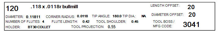
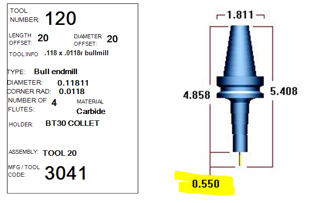
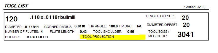
Thanks! The "OVERALL-LENGTH" tag works perfectly. I changed the tool shoulder length to .45" with a tool stick-out of .55". The output now shows the corrected values: I will also get an XML file viewer to better understand the relationships. Is there a manual or other source I can reference in the future that has more accurate information than the "Setup Sheet XML Outline and Tag Glossary"?
-
Hello, I am attempting to output the tool projection length from the tool holder face using "[spAssembly]" and "ToolProjection" tags that are listed in the "Setup Sheet XML Outline and Tag Glossary". So far, I have had no success. The only way I can show the length is to output a graphic view of the tool assembly which dimensions the tool projection with the total holder length. This uses a lot of paper since I am using many different tools. Can you show the method of adding this and other functions to my Active Report? The upper graphic is the holder assy. output and the lower graphic is where I would like to display the tool length. Currently, I have to set the "Tool Shoulder" length to the tool stick-out length in the Mastercam tool manager, then output the tool shoulder as the tool projection output value. The tool shoulder output value is easy to get but the tool projection is not. Thank you.
-
I am not certain because versions 2017 and 2018 work fine on the same computer and graphics card.
-
Hello I have been using Mastercam version 2019 for a short time and I have noticed the line width for all geometry is displayed at the narrowest setting. I can set the width to the widest setting and draw geometry but it is displayed at the narrowest width. When I analyze the geometry, the result shows at the widest setting. When I right click on geometry and change the width to a larger setting, the geometry displays the same narrow width. Once again, it analyzes as full width. My on-screen fonts also stay at the narrow width and the result is small gaps in the characters both on screen and when printed. The printed output is difficult to see because of the narrow width of the font characters and geometry. I have not had these problems with previous versions of Mastercam. I checked the status of the "Entity Attribute Manager" in settings and it is not active. I also compared my settings with Mastercam 2018 and 2017 to the 2019 settings and found them to be the same. The line width controls work fine in the other versions. Is there a new setting or method in 2019 which locks out this adjustment or could a graphics card/computer issue be the cause in 2019? Thanks.
-
Sorry for the long delay. The machine dealer suggested some methods to check the machine's internal pivot position, but the failing G68.2 option prevented these from working. Finally, the machine dealer sent a tech out to see our machine's behavior when trying to use G68.2. The verdict is........ the parameter values for the X, Y and Z axis were set at the time of install to INCH values when they should have been set to METRIC values. So, the rotation pt. used to compensate the G68.2 was really far off location, resulting in the large position display change. Now we know. Thanks to all who contributed.
-
On the response with the screenshots, the top screenshot is the program position X3.0 Y0 and Z15.77254 when the program is started. This is the X and Y pos. relative to the program coordinate system origin and the center of rotation, since they are the same pt. The program next calls the rotation of B-90. and C0. before the G68.2. The next screenshot is after the G68.2 is read. The position screen values change, but the machine doesn't physically move. The next screen shows after reading the G53.1. The position screen changes again, but the machine doesn't physically move. The last screen shows the G54.1 P20 position on the lower right (G54.1 P19 on the lower middle) and the ABSOLUTE pos. display after the G53.1 is read. I don't know if the coordinate system values can help to figure out the position shifts.
-
The machine is a small table Fanuc Robodrill vertical mill, with a B axis tilt (about the Y axis) and a C axis rotate (about the Z axis when the B is at 0 deg) trunnion style table. The rotary table is mounted on the left end of the machine table. My G54.1 P20 coordinate system is currently at the center of rotation of the B and C axis from the machine home position (X0 at left, Y0 at back and Z0 at top). The view perspective is from the spindle down to the table is Z minus dir., X+ toward the right and Y+ toward the back. The B tilting axis is limited to +17 degrees (X- dir.) and -107 degrees (X+ dir.) while the C rotary axis has no limit (+/-360 degree rotations). I hope this helps.
-
Do you need G68.2 if you use G54.4? I have taken screen shots of the positions at each stage: First is the start pt of X3.0 and Z15.77254 (machine is at Z home pos.) Next is at the G68.2 which equals X15.77254 and Z-3.0. Next is at the G53.1 which equals X21.33974 and Z3.80922. Last is my G54.1 P20 offset showing X3.31879 Y-7.59905 Z-15.77254 B-.0097 and C315.760. When I MDI G69 in the control, the X returns to X3.0 ans the Z returns to Z15.77254. For a B-90 C0 rotation, the G68.2 line shows I270. J90. and K90. A sample program that I have from the machine dealer shows I-90. instead. Will this make a difference and can else anyone verify these values?
.thumb.jpg.b2d1e92017f33dcdce9671ce77238cca.jpg)
.thumb.jpg.14b8d6a788116c239a7e81e5329a91c6.jpg)
.thumb.jpg.1d8ec9a71ef0c44e5db7ac39f1e3b6c6.jpg)
.jpg.664e13404162dd7eacc46c015075481a.jpg)
-
Here are the parameters: para. #19746 = 0 1 0 1 0 0 0 0 #19696 = 0 1 0 0 1 0 0 0 #19680 = 12 #19681 = 4 I hope this helps..
-
The post outputs XYZ positions after the G68.2. I would like to know if a program with G68.2 will have the same XYZ moves as one without G68.2? The post currently outputs the same tool motions with or without G68.2. The only differences are the G68.2, G53.1 and a G69 cancel outputs . If this seems correct, then I will look at the machine control settings. The machine is currently busy running production parts with the original program, so machine control test time is hard to come by. Getting closer to the solution, I think. Thanks
-
It seems like a machine control issue. The control is a Fanuc 31i5. The 19700, 19701 and 19702 parameters are set to the index pt. of the rotary. I don't know what other settings should be. My program origin is the center of rotation of the rotary table B and C axis and I use the TOP VIEW WCS in Mastercam. My tool path views are the same as the part orientation in the machine. I position the machine to X3. Y0 Z6. B-90 and C0 before the G68.2. After the G68.2 is read, the X becomes X6. and the Z becomes Z-3.0 . The table doesn't rotate when the G53.1 is read, so I think the IJK is correct. A G69 command resets the coordinates back to X3. and Z6. If I command a G0 G90 X3. Z6., the machine moves -3.0 in the X axis and 9.0 in the Z axis which is not the same location on the part. Can I assume that the post is not suppose to compensate for this by shifting the X coordinates by 3.0 and the Z by -9. to position to the correct location on the part? Are the program positions the same as in Mastercam relative to the origin (X3. Z6.) which means no coordinate "flipping" in the machine? Are the XYZ coordinates of the posted program after the G68.2 line the same as a program posted without G68.2? Neither Cimquest for the post or Methods Machine for the machine can offer any positive feedback as G68.2 seems like an option that is not often used. I have not contacted Fanuc yet. Thanks to all for the help.
-
I will be probing each part in the machine to set the origin relative to the actual part location, so I don't think the origin will be exactly at the machine center of rotation. It is going to change for each part. The question I have is : do I set the coordinate system to the new part origin with the machine using the settings in the parameters for the actual machine pt. of rotation, or do I set the coordinate system to the machine pt. of rotation and put the part origin shift on the G68,2 line using macro variables for the XYZ ? Will the G68.2 function work better with the Mastercam origin on the part rather than the center of rotation? These may be questions for the Fanuc tech. to answer. Thanks again, and have a great weekend as well.
-
My origin in Mastercam is the center of rotation of the B/C rotary, TOP VIEW is WCS and my views are as the part looks in the machine. In a test program, I position the tool at X3. Y0 Z6. B-90 C0 and the ABSOLUTE pos page on the control shows these locations. After reading the G68.2, the X becomes X6. and the Z becomes Z-3. without the machine physically moving. A G69 command sets the positions back to X3. and Z6. When I command the G53.1, the rotary axis does not move so I think the IJK post output is correct. Does this mean that the post should compensate the X and Z axis output to X6. instead of X3. and Z9. instead of Z6.? Or, should the post output the same locations as in Mastercam relative to the origin pt and the machine control internally compensates the position? It sounds like a machine control issue. The control is a Fanuc 31i-A5. I have not yet been in touch with Fanuc for an explanation of the G68.2 option behavior. Currently, we segregate the parts into lots with the same location characteristics. We then run the parts with the program that matches the part location in the fixture. There are several programs in the machine to match the variety of part lots. The plan is to probe every part in the machine, set the coordinate system to that part and to use the same program by following the new part origin location using the G68.2 option. I have used G54.4 at other shops, which is an easier option to use but this company has only the G68.2. Thanks again for the responses. It has been frustrating dealing with the post company and the machine dealer as they have very little experience with these options.
-
Thanks for the responses! I tried the link that civiceg showed in his response. I don't know if that is a head/head machine as mine are table/table machines. I am not familiar with the differences program-wise. Also, his coordinate systems are located on each face and not on the center of rotation, so when I initially posted it, I got no G68.2 output since all coordinate views were in the Z axis at home rotation pos.. When I changed the "Working coordinate system" tool path views to top view, I then got the G68.2 output. The origin pt. is too close to the views to show a noticable coordinate system rotation from the G68.2. Leon82 sent a sample program with G54.4 in it. This was an option I used on Mazaks a number of years ago, but these machines don't have the option. The Y axis output seems large, so is that a result of the post compensating for the G68.2 rotation, or is the part located -10.4 from origin? My machine is a vertical machine with a B + C axis rotary table mounted. The problem I referred to was the X and Z axis swapping coordinates in single block mode at the G68.2 line. The X was 3.8521 and the Z was 15.7736. After reading the G68.2 line, the X became 15.7736 and the Z became -3.8521. Is this normal? My post doesn't compensate for this rotation. Thanks again, but still confused.......
-
Hello! This may be an old subject, but I can't find what I have been looking for. I am programming a Fanuc Robodrill 5 axis mill (B-C rotary table added). I am trying to probe each part before milling to establish the part origin pt. and use G68.2 feature to follow the part origin. The G68.2 option was added to the machine last July and the Mastercam post was finished a couple of months ago. The machine was tied up until last week, so I couldn't try out the option until last week. The rotations output from the post seem to match examples I have found on the internet and from the machine dealer. The problem happens when I execute the G68.2 line in the control. The X and Z positions in the ABSOLUTE pos. page switch for a B-90 C0. rotation . The X becomes Z and Z becomes the X pos. I can't find an example of a G68.2 program output to determine if this is normal. My post outputs the X, Y and Z in non-flipped coordinates as they would be in Mastercam . The post writer says this is normal. The machine dealer says the coordinate rotation is normal and the post should compensate for the position rotation. Neither person sounds very confident or well based in using G68.2. If you could give examples and advice on the use of G68.2 feature, it would be helpful as the job must go in the machine soon. Thanks in advance.
.jpg.42e6485f916f4083a758c19308a16f0f.jpg)
.jpg.adacf7d699569e6734755d45d110634e.jpg)
.jpg.543fedd8d7399b7caa5f1dc488c7e9fe.jpg)