dannysdad
-
Posts
78 -
Joined
-
Last visited
Content Type
Profiles
Forums
Downloads
Store
eMastercam Wiki
Blogs
Gallery
Events
Everything posted by dannysdad
-
It is a Mazak Nexus 6000II Horizontal. The G10 are a set of G54-G57 locations that we use most often. These are changed if a different tombstone with different parts are used. Since we run the parts with those G10 numbers most often, we have that set as our default.
-
OK, that worked. I am going to redo my pallet and try on that. Thanks
-
No, I got nothing for a "B" output.
-
Thanks....I will give it a shot.
-
I am going to plead complete and total ignorance here. What is the MD? What is the CD? The Post I am using is a custom horizontal 3-axis. I tried both combos that you suggested on WCS/Tool plane on two different sides. I tried on every side of the tombstone and the post outputted the same B90 for every side. I appreciate your help...I am afraid I am going to have to wait for a hands-on from my reseller....I am in over my head and now I am getting more confused.
-
Thanks, let me give that a shot. I am using a custom WCS, I have it set for the surface and lower right corner of my part.
-
Yeh, I contacted my reseller yesterday with the problem.....don't know how long it will take for them to get back with me. I thought I would give the forum a try. Maybe ya'll would have a quick answer. It looks like I am going to need a little bit more instruction via GoToMeeting.
-
Ummm. I am not exactly sure what you are asking. What should be the top/ ? What should be the /front or top/ ? And what should be the /top ? Bear with me...setting the WCS and planes has always confused me.
-
I work exclusively on tombstones. I have just run into a problem I do not have an answer to. The tombstone and clamping fixtures are drawn. I drew the flat stock and affixed it to the B0 side of the tombstone and ran my toolpaths (some drilling and a slot). I set my WCS and had my construction and tool planes set on the milling face. When I ran this through my processor, the post generated that the face I was working on was B90. This will not work. There are a lot of instances where I need to start work on a certain face (B0, B90, G180, B270, B45, etc…) and I need that particular face generated in the code. Is B90 a Default? Is it a product of the processor? Is there a way I can fix this using WCS? I need a way so that if I start out working on …say, the B180 and then rotate to the B270 side to work on that face of the part, (which I will need to do quite often in the future), I will have control that the processor will generate what I need. It is time-consuming and counterproductive to have to go in and edit every rotation, not to say quite dangerous and expensive. (MAZAK HMC MATRIX 5-7-12) (MACHINE GROUP-1) G91G80G28Z0. G91G28X0.Y0. G10G90X-13.98Y-15.166Z-20.514P1L2 G0G28G91Z0.M9 M1 ( T105 | 15/32 .469 ISCAR DRILL | H105 ) G20 G0 G17 G40 G80 G90 G91 G28 Z0. N105 T105 T0 M06 M699 T0 G0 G90 B90. <<<<<<<<<<<<<<<<<How Do I Make This B0??? S693 M3 M51 G0 G17 G54 B90. X-11.2186 Y3.0155 G43 H105 Z.1 G99 G81 Z-1.5953 R.1 F7.6 X-9.5311
-
All right, that is what I resorted to this morning when I couldn't get it to work using one operation. However; I did learn something new this morning and that is always good. Thanks again.
-
OK, just by using the "depth cuts" branch only, I was able to control the depth of my cuts....thanks. But another query, is there a way to control the feed on the second pass using this method?
-
Mr. Paris, I am still doing something wrong. I have no problem setting the top of stock to .002, however when you say; "make sure you have 2 finish cuts at .001 distance", I am not sure where this has to be done. Is it on the roughing, finishing or depth cuts page? And what box do I check and/or fill out? I am so confused.... Thanks.
-
Hey man, I made a mistake.... I am not using "contour", I am using "circlemill". Is it possible using circlemill?? Thanks
-
I am trying to clean up the face of a 1.562” circular boss with a .625” solid carbide endmill. I only have to remove .01” from the face but I want to leave .001” for a finish pass. I tried to do this process using “contour”, but the roughing pass kept going down to Z0. I couldn’t figure out how to leave that .001” for the finish pass. Am I using the wrong process?
-
Oh boy, never thought of that!!!!! Thanks guys!!!
-
I am milling a chamfer on the outside of a 1.625 boss with a 1.02", 45° Chamfer Mill. Using Mastercam, I can only use conventional milling….no? Yes? I do not see any way to reverse direction to climb-mill. I would prefer this method because it is not so hard on the tools. Any ideas?? Thanks P.S. I am leaving work soon so if anyone responds, I will not reply until morning. Thanks
-
Thanks John and Jason I learn a little something new every day.
-
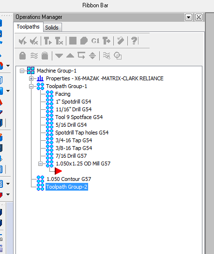
I am running X6 and I have been having this problem the past few days. We run quite a few family of valves that are milled on castings on a 4-square tombstone that maintains the same work coordinates every time. It is mostly facing, drilling, tapping and threadmilling (ID and OD), and some counterboring. So once I get one part done, I can just rechain geometry to make a slightly different or mirror image of the original. So I take the original file, make my changes, rename the file and I have a new part. Here is the problem. I make the changes, make sure ALL of my processes are selected, hit the "post all" button and wait for the post. However, not all of the selected items will get posted. This is happening more and more often, even if I select two or three processes together to see if my indexing is correct. If I select the dropped processes by themselves however, they will post....just not with the entire process!! Frustrating!! So I am forced to post out processes in pieces and edit them together. This is not fun and it is time consuming. Considering I have over 100 variations on the same valve, this is totally unsatisfactory. Anybody know what I am doing wrong or have a solution? Thanks in advance. Chris
-
Thanks Josh, That was the ticket. Now to find a new itch to scratch.
-
Hello Gurus, Almost a year into Mastercam and you would think I would know this....but I don't. How do you make a Tool Library default for a particular machine? For the life of me, I cannot figure it out. Everytime I start a new file, I must change the tool library. No biggee, it just bugs me. Thanks
-
Hello friends, Well I did not have the backup turned on....so I am screwed. Learned a valuable lesson though. My backup is NOW turned on. Thanks for your help. Cheers, dannysdad
-
AAARRRRGGGHHHHHHH!!!!!!!!!!!!!!!!!! I was trying to delete an unused toolpath, so I rightclicked thetoolpath, hit delete.......ALL my content is gone!!!! Just the names remain, no toolpaths. Then I doubled down on my goof and "saved" my error. Is there any way to retrieve my work???

-
Will do...thanks.
-
Sure Pete, I am getting ready to walk out the door right now...can I send it tomorrow? Where do I send it?
-
I saved it as a .stl file, this is what I got. What am I supposed to do with this? Did I save it wrong?