


AlbertZini
-
Posts
179 -
Joined
-
Last visited
Content Type
Profiles
Forums
Downloads
Store
eMastercam Wiki
Blogs
Gallery
Events
Posts posted by AlbertZini
-
-
Somebody can show an example of how to Use Safety Zone ????????
-
I understand you, Thank you [email protected].
-
Yes, I want to create one that would take less memory in the machine
If I change the surface quality the program - cut tolerance is reduced but there is little movement on the X in 0.001 and shows a bad verification,but in cimco shows the correct path
Maybe somewhere there are filters?


-
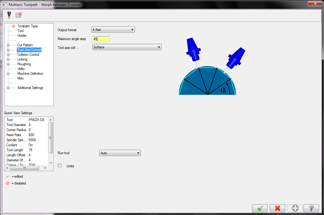
its the MAXIMUM angle step .. so any step from 0 to 45 is possible.
I think that's what it means.
Rogkick how to set the minimum step ?
-
Why when I write angle step 45, he does not change in program,

in programm i see
A-44.833
A-46.67
A-48.507
A-50.343
A-52.179
A-54.013
A-55.848
A-57.681
A-59.515
A-61.347
A-63.179
A-65.011
-
It appears as though you have your "convert rapid to maximum feedrate" option selected in the control definition. Open your control definition under the settings menu, select the feed menu and uncheck the appropriate box.
No, this option is not enabled.
I turned off the first entry in linking and everything became good, but the question remained with angles
-
1.Why when I write angle step 45, he does not change in program
2.And the output feed in the wrong place
%
O3171
(PROGRAM - O3171.NC)
(DATE - MAY-15-2013)
(TIME - 7:23 PM)
(T4 - ENDMILL D8. - H4 - D4 - D8.000mm)
G01 G17 G21 G40 G80 G90 ( -------------------- need here G00)
G91 G28 Z0.
(COMPENSATION TYPE - COMPUTER)
T4 M06 (ENDMILL D8.)
G01 G17 G90 G54 G94 A-40.45 X-93.325 Y-23. S5500 M03 F600. ---- (G01 & F600. in wrong place, need here G00)
G43 H4 Z44.396
M08
Z36.001 ----------------------------------------------- (G01 & F600.need here )
Y-11.5 Z35.946 A-40.803
Y-5.75 Z35.977 A-40.979
Y-2.875 Z35.991 A-41.067
Y-.719 A-41.133
Y0. Z36. A-41.156
A-42.994 F954.9
A-44.833
A-46.67
A-48.507
A-50.343
A-52.179
A-54.013
A-55.848
A-57.681
A-59.515
A-61.347
A-63.179
A-65.011
A-66.841
A-68.672
A-70.501
A-72.331
A-74.159
A-75.988
A-77.815
A-79.643
A-81.469
A-83.406
A-84.966
A-86.792
A-88.616
A-90.441
A-92.265
..............
..............
-
I understand what you mean,i want to use cutter compensation only 4 axis , when there is a milling left or right side of mill
-
in Mastercam 9 has SODICK A280L and SODICK A350W and SODICK MARK30
-
Thanks for the reply EX-wccprogrammer now I understand you.
When a lot of parts with little tolerance 10-0.02 mm we must regenerate a program that would go to that value or compensation to write by hand
-
If I understand correctly is responsible for this procedure "pccdia"
and for compensation for tool in my case "15346-2 compensation type = 2 wear". "15347-0 compensation direction. 0 = left"
But I do not understand how to write correctly in the post, and why compensation is disabled when the multi-axis is enabled
-
If I turn on the tool compensation - "COMPUTER" "CONTROL COMP" "WEAR COMP" "REVERSE WEAR COMP"
is not that the program is not changed
(T219 - 10. FLAT ENDMILL - H219 - D219 - D10.000mm)
G00 G17 G21 G40 G80 G90
G91 G28 Z0.
(COMPENSATION TYPE - WEAR COMP)
T219 M06 (10. FLAT ENDMILL)
G00 G17 G90 G54 A0. X22. Y0. S1909 M03
G43 H219 Z120.
Z30.
G94 G01 Z20. F190.9
X15. ---------------- G41 D219 X15. F381.8(need cutter compensation)
A4.091 F1093.8
A8.182
A12.273
A16.364
A20.455
A24.545
...........
...........
...........
A-40.909
A-36.818
A-32.727
A-28.636
A-24.545
A-20.455
A-16.364
A-12.273
A-8.182
A-4.091
A0.
X22. ---------- G40 X22. (need cutter compensation)
G00 Z30.
Z120.
M05
G91 G28 Z0.
G28 Y0.
G90
M30
%
Please how to implement it !!!
-
 1
1
-
-
How to enable in Mpmaster postprocessor - cutter compensation in multiaxis ("4 axis") strategy ?
-
1
-
-
[
if i$ <> 0 | j$ <>0,
[if sqrt(i$^2 + j$^2) <mr4$ ,feed = feed*mr3$]
],
and how to do it, if I use the radius in Generic Fanuc 3X Mill?
-
This what you want to end up with by changing your to tilt away from a point.
Thank you Jay!
Why are you doing this in X5 if you have X6 and I am taking you are not a dealer correct?
5X and 6X are on different jobs
-
To you have multi axis option?
Yes
Other wise use 3D paths to rough each slot and index to the next slot and do the same. so program one slot and use tool path trransform use the rotation and toolplanes
I know how create a roughing in 1 operation - Parallel to multiple curves
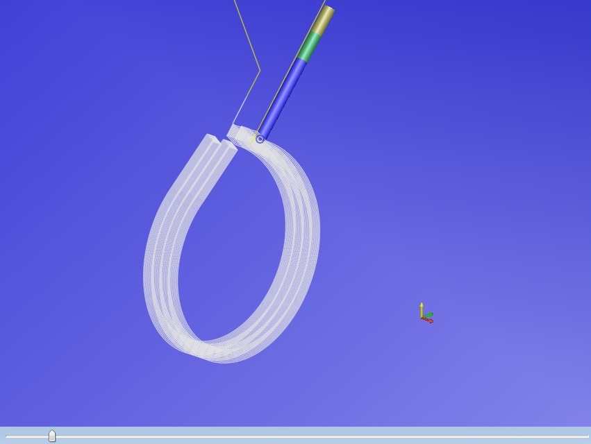
But I want to create a roughing in 1 operation - Morph between 2 curves - this is possible?
Can you show by example, how to do it
-
How to create a rough 4-axis milling ?
-
I found a knowledgeable person who develops post processors
and he told me how to do it
create sudptooltable and write him in ptooltable
-
Thank you all, I did it
-
So...
You wish to be able to output X,Y,Z limit info
Within the toolable at top of the file ?
and/or
At each toolchange?
And also have the overall program limits ?
See XYZ_LIMITS.ZIP
(In the "/Mastercam_forum/Text_&_post_files_&_misc/" folder of the FTP site)
Roger Martin could you show how to conclude the depth in one line
%
O1111
(DATE - MAR-30-13)
(TIME - 12:51)
(T20 | 5.0 CENTER DRILL | H20 | D20 | Max_Z = 5. Min_Z = -.3)
(T12 | 3.8 DRILL | H12 | D12 | Max_Z = 5. Min_Z = -2.392)
(T13 | 6.25 DRILL | H13 | D13 | Max_Z = 5. Min_Z = -3.128)
(PROGRAM AXIS LIMITS)
(Max_Z = 5. Min_Z = -3.128)
G00 G17 G21 G40 G80 G90
.....
.....
-
Thank you all, I did it
I found a knowledgeable person who develops post processors
and he told me how to do it
create sudptooltable and write him in ptooltable
-
-
That was mode the the German group. Do a Google search and you will find their web site. Try emailing them and see if they have something they can share.
I downloaded this app on ftp ftp://mastercam-cadcam.com/Mastercam_forum/X6_Addons/Clamp-Setup_X6_32-64Bit_V30.rar
-


Tool inspection/change
in Post Processor Development Forum
Posted
Somebody knows how to implement this feature in the mpmaster or generic 3axis fanuc post?