


Chally72
-
Posts
499 -
Joined
-
Last visited
-
Days Won
32
Content Type
Profiles
Forums
Downloads
Store
eMastercam Wiki
Blogs
Gallery
Events
Posts posted by Chally72
-
-
Right now, the new Machine Group Setup flow is, as you pointed out, structured around one setup per machine group. I typically work with one machine group and setup flips in toolpath groups within it. Because of that, I would continue using the pre-2023 workflow for those situations.
Today in the new Machine Group Setup flow, there's not much incentive to switch your flow if you're a power user with complex product, because all of these changes so far are aimed at easing and guiding single-setup experience, rather than the super-efficient flow we've all fallen into. In the future, this Machine Group Setup will expand in two ways:
-Give reasons/benefits for you to set up master model, workholding and multiple stock. IE, make toolpaths look at these and make better decisions upfront so you have to spend less time repeatedly telling each toolpath the same thing.
-Expand the capabilities available to you in a single Machine Group. Think, handling of tombstones, stock flips, etc, to move that power-user flow into the new Machine Group experience.
-
 2
2
-
 1
1
-
-
I'll take a crack at answering blind-
Your pattern result and the curve it has taken on is a reflection of the pattern selection and curve geometry. I'm guessing you're using Parallel or Guide, and you've chosen an edge shorter than the part width as the curve to stay parallel to. There are a few controls that affect how the pattern echoes out from the chosen curves-
If Guide cut pattern-
Turn on Straighten Cuts on boundaries on the Machining Geometies subpage under Cut Pattern
Turn on Extend open input curves on the Guide Curve- Advanced subpage under Cut Pattern
If Parallel cut pattern- Turn on Extend edge curve on the Parameters For Surface Edge Handling subpage under Cut Pattern.
With Unified and multiaxis paths especially, there are so many options and ways to set up your pattern and trimming, it helps to just post the file if at all possible so that we can offer up some examples and avoid guessing about how the path is set up!
-
5
-
-
Using Save Some, change the Save-As type to Parasolid (the native kernel Mastercam uses). This removes all Mastercam-specific items such as viewsheets/etc, while leaving the entities intact and untranslated, and the file can be opened directly in Mastercam. When saving out to STEP and reimporting, in the background you're changing the data format from parasolid to STEP then back to parasolid, which can induce translation errors.
-
1
-
-
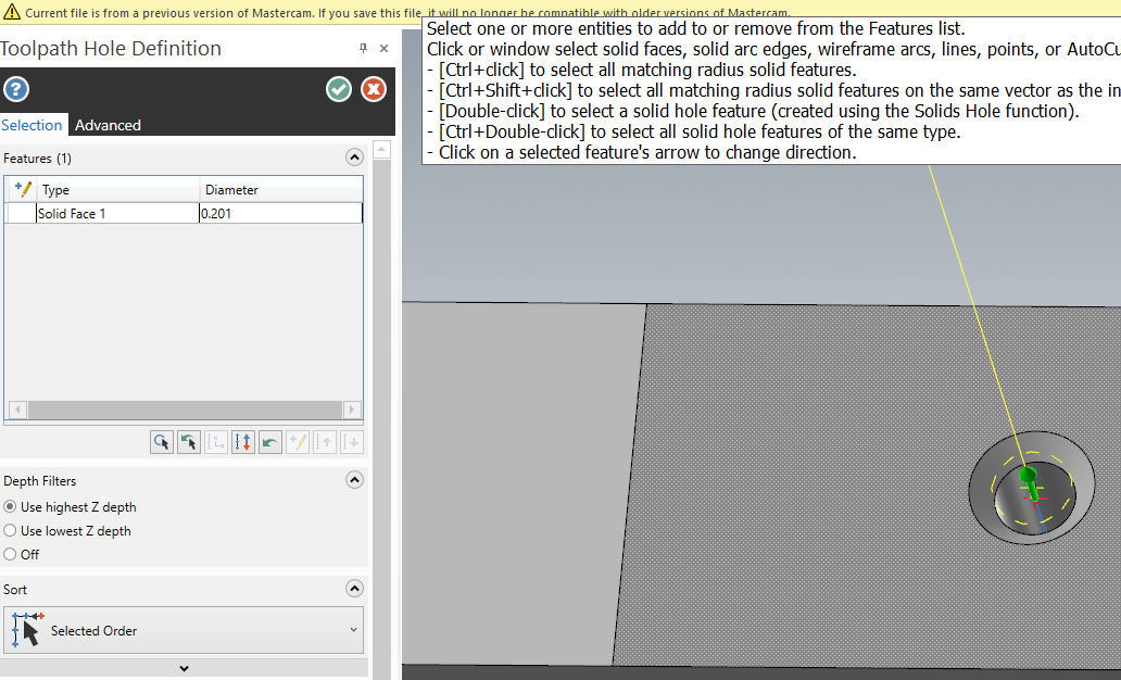
2 hours ago, IbanezTim said:
Ok, I am dumb or brain farting..... I for the life of me cannot figure out what I am doing wrong here as I can not get Process Hole to recognize that i have tool paths in here. Where has my brain turned off?
Hey Tim,
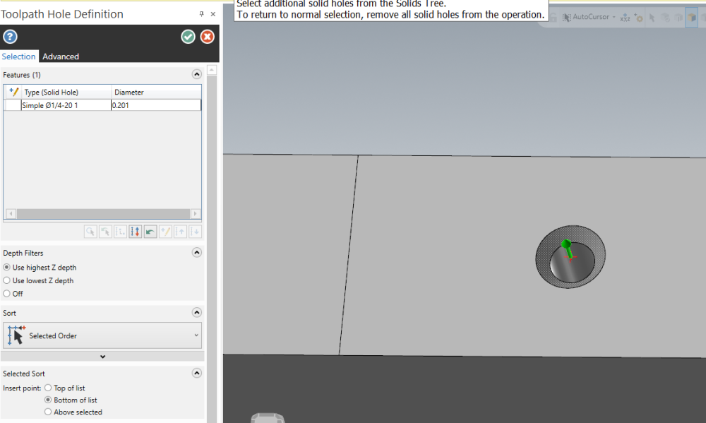
Process Hole works by matching Solid Hole forms (and segments of a hole) between the template file and the part file you're using Process Hole in. Because of this, the selections you make in a template file need to be tied to Solid Hole operations, or they're just ignored by Process Hole as invalid processes for a template file. (This helps you use any part file as a valid template file, and filter out any toolpath groups or operations that aren't part of the template process you would want to use.) This solid hole selection distinction can be subtle and it's one of the things we're working to improve in Process Hole.
So, simple change to make it all work. Here in your template file, you've single-clicked and selected solid faces (no intelligence) for the features the toolpath is acting upon:

Instead, double-click to select the actual solid hole (intelligence, knowledge of the solid operation and all segments of the hole). Take a look at the differences in the Toolpath Hole Definition labels and name. The Type is now signified as (Solid Hole) and the name of the feature is the name of the solid hole operation.
-
1
-
1
-
-
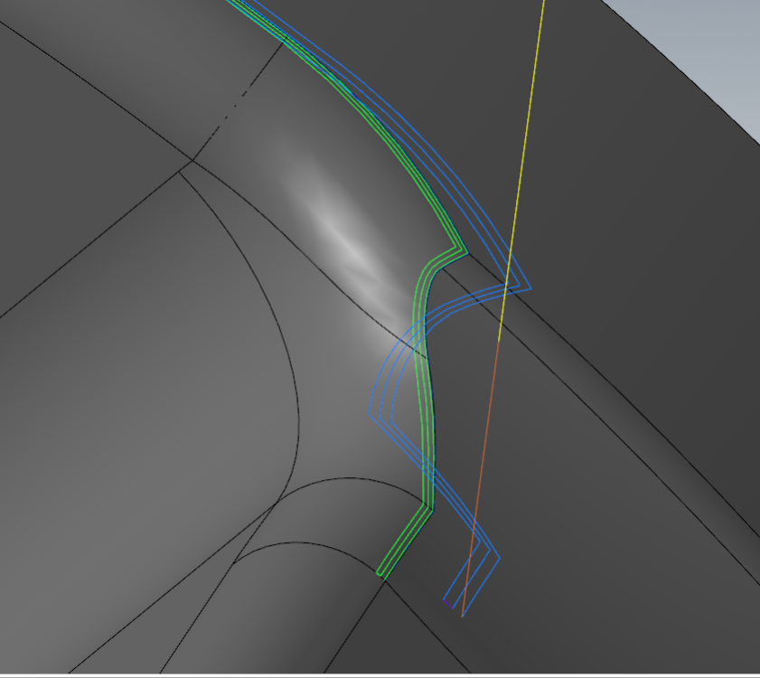
Here's my favorite little example of this- a simple 3 axis path with a ball tool traversing across a variable fillet where a blend or morph might be used. If I was looking at this like I usually do, I'd see those blue lines and I might as a programmer instinctually say "This path is no good, I have to go fix this or play around with parameters here."
But, if I'm looking at the green in the image below, (actual tool contact point,) I'm getting a very different perception of the path....IE, leave it alone, it was fine to begin with!
-
3
-
-
I don't have Aaron's file, but I'd guess that the "jankiness" is the tilt being applied to the tool/holder to avoid the walls as the tool pivots through the corner. Remember that when you're looking at the blue lines, you're looking at the tip position of the tool, and NOT the actual contact point of the tool flute to the surface. The Collision control method may be modifying the tilt, which will pivot the tool about the center of the ball, not about the tip, and it'll swing the blue lines up and over and make them appear uneven.
If you plotted out the actual contact point (or had a way to view it, which you do in Simulator in 2024 and will in Advanced Toolpath Display in 2025), you'd see perfectly crisp stepovers still. And the examples farther up the thread were in some cases looking at the pattern before collision control was applied, meaning the blue tip still represents the true stepover at this stage.
If you've ever calculated a toolpath using an accelerated finishing tool, this disparity between where the blue lines fall and what the tool is actually doing is even greater, since the tool effective radius centerpoint does not fall along the tool centerline, and small changes in tool flute contact can create major disparities in pass to pass tip position visuals. The "gut check" we get by looking at the blue lines for uniformity becomes less and less valuable as a measure of the quality of the path.
-
3
-
2
-
-
The level they're assigned to is -25, which is a system level. You will have difficulty removing entities on these levels and if their visibility is on you won't be able to change them. Certain commands in the software will create and blank geometry in the background. An example is surface trimming. Some of this blanked or hidden geometry is intended to be accessible, and some is not. 2023 Updates and 2024 do a better job at making sure you cannot inadvertently make visible some of these things through the course of certain actions like Unblank (though there are other triggers)
-
Those are likely background entities created and used by drilling toolpaths, among others. They should not be visible normally. Taking certain actions in Unblanking can inadvertently bring them to light, among other things. The later 2023 Updates and 2024 contain fixes to ensure these entities stay hidden.
-
2
-
-
Changing a tool stickout length, or any tool or holder geometry/heights, is changing a critical part of what a toolpath is calculated with. The toolpath must be recalculated after these changes. Your question might then be- "why does it have to recalculate if I'm increasing projection, as that would theoretically be additional clearance and no collision risk?" But this does not account for scenarios where the tool, holder, stock, part, or fixturing is placed in an undercut scenario, and thus we can't assume that increasing tool projection will always be safe.
-
1
-
-
This is currently slated for Update 3
-
5
-
-
This and some other Thread Mill entry capabilities are currently in the works, stay tuned....
-
2
-
-
Check the Orientation option when creating a Bounding Box. I believe default is to orient the box to the Construction plane, and you probably want Auto, because you want to fit the smallest rectangle to your geometry regardless of orientation in space.
-
2 hours ago, TacoMachinist said:
Anyone having an issue with 2024 just adding random tools when making toolpaths?
In previous versions if I only had 1 tool in my tool list it would just default to that tool. but now its just adding a random tool that I don't know the source of?
For example: I was just starting roughing and only had a 1/2 endmill with a 1" flute length (the only 1/2 endmill in my library). Next operation and skip the tool page since there's only 1 tool and it added a 1/2 endmill with a .5" flute length. this tool doesn't exist in any of my libraries so I have no idea where it came from..
I just tried to reproduce this but couldn't. Now, if your next op is something that can't use the one tool you inserted into your library (like a bull tool for model chamfer) the tool from the .mcam-defaults file for that operation would be pulled in instead. The tools you're seeing pulled in are likely all the default tools for those ops in the .mcam-defaults files.
-
Tinger, is this part of the same tool library you were having loading time issues with? If you haven't already, please send this projection issue in to tech support as well for them to look at.
-
-
On 6/10/2023 at 7:58 AM, SlaveCam said:
Does 2024 still have the bug where finish speed & feed (thread mill) get copied into normal speed & feed?
This was caught late last year and is being considered for a 2024 Update. Thanks.
-
The intention is not to force a new machine group for every setup, for many reasons but Ron listed a big one with duplication of tool libraries and such.
Fixture definition (and stock and position) for Simulation in 2023 and earlier used to be the same set for every machine group in a part. So if you were switching between machine groups, you'd have to redo those settings constantly, as well as if you were switching between different setups in the same machine group.
2024 was a step in moving towards saving these setups so that you're not redefining them every time for the clearly different scenarios you're encountering between setup changes and machine group changes. There's still more to be done, but the general idea they're moving towards is that you're defining these things once and then reusing the definitions wherever possible, to eliminate the need to constantly switch level set selections when examining different areas of your toolpath tree.
-
1
-
-
1 minute ago, OVodov said:
I'm really like improvements of using Stock Model as updated Stock for simulation.
One thing is annoying me right now from Stock Setup it's still doesn't support multistock for many parts at once
There are some technical reasons that this can't be done yet, revolving around how older toolpaths function and some assumptions made on a single piece of stock. Those must be solved first in a way that does not negatively affect legacy files.
-
1
-
-
11 minutes ago, neurosis said:
Right now, I'm working on an assembly that has several parts being programmed in the same file. I don't want to have to create separate files OR Machine Definitions for each assembly component just to be able to verify tool paths. I was able to do all of that very easily in 2023. Can you tell me if there is some kind of workaround for that type of work flow?
----
I'm able to get around this removal of functionality (stock creation) by creating stock models and selecting them to verify. <--- I'm not explaining this very well. I can create a stock model and without creating any official stock , just select the stock model and it automatically uses that for the verify stock. Really cool.
This type of workflow is not well-catered to yet. You'll have to continue to swap the level selection set back and forth like previous versions of Mastercam, but you'll do it in the MGS Workholding panel now. The sim team has some ideas for where to go with this in the future....
-
Just now, rgrin said:
So are you saying if I have a stock model at the top of my toolpath like I have here, then verify will automatically select that model for the simulation? That seems pretty neat.
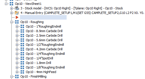
Yep, exactly! This was an important one for me- I like to do a lot of "in-situ" verifying of some set of operations deep in the toolpath tree, and not having to keep setting Simulator options to look at Op 153 or Op 171 or whatever stock op was preceding the ops is a great change to allow me to bounce around quicker.
-
4
-
-
15 hours ago, neurosis said:
Can you use stock override to create a bounding box using stock corners? Or can you select levels to add fixtures like you could in 2023?
Stock override uses things that are already created and stays associative, so you can't create a random bounding box in just that panel tab at the override location- you'd create it elsewhere and set it as the override here. Removing duplicate locations to enter/specify the same data is one of the sim team's goals with improving MGS and the simulation experience.
The levels selection still exists in a different manner in 2024 for Workholding, and I agree that the flow can improve. I don't know what they may have cooking for that.
50 minutes ago, nperry said:I keep reading about issues people are having with stock models with 23/24 and it's always made me wonder because I don't have the same issues, but now I'm curious about it. I never use bounding box, I always make a solid of my stock on another level. I also never use "stock setup" to verify anything. Right off rip, create solid and input into stock setup, then start file with a stock model before any toolpaths, run first ops, if they need to be stock aware, off of that stock model operation. Verify off of that stock model instead of stock setup.
What I don't understand about your scenario is when are your OP1 paths actually going dirty? What's the actual moment ("activating" as you put it) where your paths are going dirty?
With your flow, you'd never have an issue because the Stock Definition you set up in MGS is only ever used for sim, and your toolpaths are associated to the stock model operation, which is associated to the solid you drew for stock. If toolpaths are instead referencing the Stock Setup selection in MGS, then that means the user can't change the Active Stock in Stock Setup without the consequences of dirtying a toolpath. This is where the methods of overriding stock in simulation have to appear in order to allow the user to experiment at will without affecting the integrity of their toolpaths.
-
1
-
-
If you go into the Simulator tab of Machine group setup, there is a Stock Setup Override in 2024 to explicitly allow this behavior.
Additionally, if you launch into Verify and a Stock Model operation is the first choice in your toolpath manager selection set, it will use this Stock Model Operation as an override as well for Verify stock- so no need to ever change Simulator Options to quick-verify an operations set with a different stock model operation.
-
1
-
1
-
-
It skips over the activation box, but if you have tip comp activated the tab order goes through the tip comp fields correctly. There's a limitation there I believe because that control changes to Break Through depending on the holemaking toolpath, which messed with our ability to add it to the tab order.
-
9 minutes ago, volitan71 said:
I think we're both misunderstanding what they mean. This is what I'm talking about, from 2022. I selected a whole group of operations and did this to them:
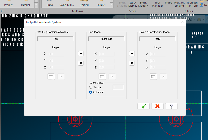
Before 2024, if you were mass editing a number of 5 axis operations with the same WCS but different toolplanes, the Edit Common Parameters would overwrite every plane- WCS, C, and T. What was lacking was the ability to only overwrite or change WCS, and let the collection of edited ops retain their disparate toolplanes/Cplanes. Now in 2024, you can deliberately choose to overwrite only one type of plane, or overwrite all.
-
2
-


Avoidance Geometry Bug
in Industrial Forum
Posted
There have been several causes that have the same end effect- an incorrect (bloated) entity count. It is not falling on deaf ears